Do you have a question about the ADTRAN MX2800 STS-1 and is the answer not in the manual?
Lists major features like redundancy, hot-swappable cards, power supplies, SNMP/Telnet.
Describes the organization and layers of the STS-1 frame.
Details AC and DC power requirements and connection methods.
Steps for installing mounting flanges on the MX2800 for rack placement.
Details the 8-pin modular jack for VT100 EIA-232 terminal connection.
Details steps for entering username and password to access the Main Menu.
Configures STS-1 network settings like line length, timing, and protection.
Manages VT settings, mapping, state, coding, and protection.
Configures IP addresses, subnet mask, and management port settings.
Resets the unit to factory default configuration parameters.
Instructions for updating unit software via XMODEM or TFTP.
Initiates loopback tests for VT/Port channels, with various test types.
Performs loopback tests on the STS-1 path with different activation methods.
Provides backup during controller card failure with two cards installed.
Offers full redundancy for both card and network failures.
Explains operation using a battery pack during AC power outages.
Lists commands for session management, user accounts, and event reporting.
Steps to establish minimal configuration for testing.
Tests traffic flow between DS1 and STS-1 ports using various methods.
Tests the CRITICAL and NON-CRITICAL alarm relay contacts.
Details the pin assignments for the RJ-45 craft port connector.
Provides pinout details for the 10Base-T Ethernet LAN port.
Details line length, rate, and interface type for STS-1.
Specifies line length, rate, code, and interface type for DSX-1.
| Product Type | Multiplexer |
|---|---|
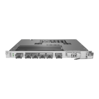
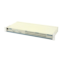
| Form Factor | Rack-mountable |
| Interface Type | STS-1 |
| Data Transfer Rate | 51.84 Mbps |
| Power Supply | AC/DC |
| Management | SNMP, Telnet |