MX2800 STS-1 User Manual Installation and Operation, Section 2
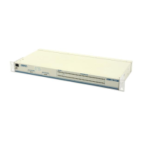
Rear Panel
61204659L1-1A 2-5
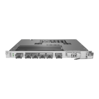
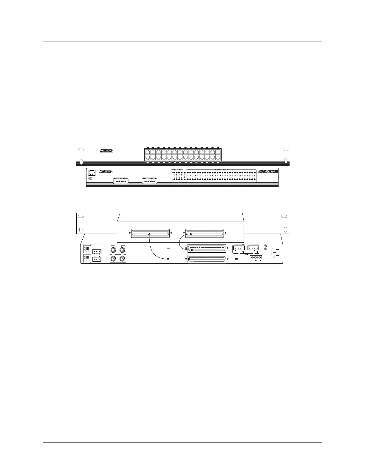
Connecting the Breakout Panel
The optional breakout panel (P/N 1200291L1) connects to the MX2800 STS-1 via the IN and OUT amphe-
nol connectors located on the back of the unit, and provides 28 RJ connectors for the individual T1s/E1s.
Shipment includes two six-foot, 64-pin to 64-pin amphenol cables which allow direct cabling to the
MX2800 STS-1. Connect the
IN amphenol connector of the breakout panel to the IN amphenol connector of
the MX2800 STS-1. Connect the
OUT amphenol connector of the breakout panel to the OUT amphenol
connector of the MX2800 STS-1 (see Figure 2-2).
Figure 2-2. The Breakout Panel
Connecting the BNC Patch Panel
The optional BNC patch panel (P/N 1200291L5) connects to the MX2800 via the TX and RX amphenol
connectors located on the back of the unit and provides 28 pairs of BNC connectors for the individual
T1/E1s. Shipment includes two 6-foot, 64-pin to 64-pin amphenol cables for direct cabling to the MX2800.
Connect the BNC patch panel
RX amphenol connector to the MX2800 IN amphenol connector and the
BNC patch panel
TX amphenol connector to the MX2800 OUT amphenol connector.
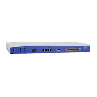
6. REAR PANEL
The MX2800 STS-1 rear panel is equipped as follows:
• LAN port
•Modem port
• Two alarm output terminal blocks
IN OUT
Cable 2
Cable 1
NET
DC POWER
115 AC 50/60Hz
0.8A
PWR
FAI L
RET
TRS TR
CLK
A
CLK
B
S
–
L
A
N
NONCRITICAL
DSX-1/E1
(OUT)
DSX-1/E1
(IN)
NO COM NC
CRITICAL
M
O
D
E
M
OUT IN
A
B
A
-48V 0.7A
B
DS3/STS-1
PWR
FAI L
RET
–
USE COPPER
CONDUCTORS ONLY!
N
E
T
A
L
M
P
R
F
A
C
T
1 3 5 7 9 11 13 15 17 19 21 23 25 27
2 4 6 8 10 12 14 16 18 20 22 24 26 28
Front View
Rear View