EasyManua.ls Logo

ADTRAN HDSL4 User Manual

ADTRAN HDSL4
2 pages
To Next Page IconTo Next Page
Page #1 background imageLoading...
Page #1 background image
HDSL4 T200 H4TU-R FOR LOCAL POWER
JOBAID
61221424L1-22A
0208
TX
RX
REM
LOC
LBK
1221424L1
DSL 1
DSL 2
DS1
ALM
(GRN)
(YEL)
ESF/SF
(GRN)
(YEL)
(GRN)
(YEL)
B8ZS/AMI
LBK/RLB
RX
M
O
N
TX
R
S
2
3
2
HDSL4 T200
H4TU-R
CLEI: T1L5J61C_ _
LED STATUS
DSL1/DSL2 Green Normal operation; signal quality (SNR Margin) is optimum on
Loop 1/Loop 2 between the H4TU-C and the H4TU-R.
Red Severely impaired operation; signal quality (SNR Margin) is 0 dB on
Loop1/Loop 2 between the H4TU-C and the H4TU-R.
DS1 Green DS1 signal from the CPE is present at the H4TU-R.
Red DS1 signal from the CPE is absent at the H4TU-R.
ALM Off No alarm condition detected.
Red Alarm condition detected either locally (H4TU-R) or locally and
remotely (H4TU-R and H4TU-C).
Yellow Remote (H4TU-C) alarm condition detected.
ESF/SF Off Indicates received DS1 signal is unframed.
Green Indicates received DS1 signal is SF framed.
Yellow Indicates received DS1 signal is ESF framed.
B8ZS/AMI Green The unit is receiving AMI line code.
Yellow The unit is receiving B8ZS line code.
LBK/RLB Off Unit is not in the armed or loopback state.
Yellow A local loopback is active on this specific unit.
Green A remote loopback is active on this specific unit.
NOTE: When used with an ADTRAN H4TU-C, the terminal screens via the H4TU-R will display
information that is stored at the H4TU-C.
OPTIONS
Faceplate Buttons
LOC Initiates a bidirectional loopback of the H4TU-R toward the network and customer
REM Initiates a loopback at the H4TU-C toward the customer
POWER
This specific unit is intended for Local Power Only. If a Span Powered unit is needed, refer to
P/N 1221426L1.
DS1 MONITOR JACKS
TX DS1 signal from CPE toward Network
(nonintrusive)
RX DS1 signal from Network toward CPE
(nonintrusive)
COMPLIANCE
Warning: The DSX-1 interface is intended for
connection to intra-building wiring only.
Ensure chassis ground is properly connected.
This product is intended for installation in
restricted access locations only and in equipment
with a Type “B” or E” enclosure.
This product meets all requirements of Bellcore
GR-1089-CORE (Class A2), ANSI T1.418-2002.
This product is NRTL listed to the applicable UL
standards.
Code Input Output
Power Code (PC) C C
Telecommunication Code (TC) X X
Installation Code (IC) A
C A U T I O N
C A U T I O N
!
SUBJECT TO ELECTROSTATIC DAMAGE
OR DECREASE IN RELIABILITY.
HANDLING PRECAUTIONS REQUIRED.
1
2
3
4
5
6
7
8
9
10
11
12
13
14
15
16
17
18
19
20
21
22
23
24
25
26
27
28
29
30
31
32
33
34
35
36
37
38
39
40
41
42
43
44
45
46
47
48
49
50
51
52
53
54
55
Chassis Ground
DS1 TX Tip
HDSL4 Tip (Loop 1)
Chassis Ground
HDSL4 Ring (Loop 1)
DS1 Tx Ring
-48 VDC Return
VCC
Chassis Ground
-48 VDC
HDSL4 Tip (Loop 2)
HDSL4 Ring (Loop2)
DS1 Rx Ring
DS1 Rx Tip
For a complete Installation and Maintenance Practice (P/N 61221426L1-5): (877) 457-5007, faxback Document 826. Please have your fax number ready.
CARD EDGE PIN ASSIGNMENTS
#61221424L1-22A#

Other manuals for ADTRAN HDSL4

Question and Answer IconNeed help?

Do you have a question about the ADTRAN HDSL4 and is the answer not in the manual?

ADTRAN HDSL4 Specifications

General IconGeneral
CategoryNetwork Hardware
TechnologyHDSL
Line Code2B1Q
Power SupplyAC/DC
Operating Temperature0°C to 50°C (32°F to 122°F)
HumidityUp to 95% non-condensing

Summary

LED Status Indicators

DSL LED Status

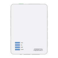
Normal operation, signal quality (SNR Margin) is optimum on Loop 1/Loop 2 between H4TU-C and H4TU-R.

DS1 LED Status

DS1 signal from the CPE is present at the H4TU-R. DS1 signal from the CPE is absent at the H4TU-R.

Alarm LED Status

Alarm condition detected either locally (H4TU-R) or locally and remotely (H4TU-R and H4TU-C).

ESF/SF LED Status

Indicates received DS1 signal is unframed. Indicates received DS1 signal is SF framed. Indicates received DS1 signal is ESF framed.

B8ZS/AMI & LBK/RLB LED Status

Indicates line code (AMI/B8ZS) or loopback state (armed, local, remote).

Power and Compliance

Power Specification

This specific unit is intended for Local Power Only. Refer to P/N 1221426L1.

DS1 Monitor Jacks

TX DS1 signal from CPE toward Network (nonintrusive). RX DS1 signal from Network toward CPE (nonintrusive).

Compliance and Installation

Warning: DSX-1 interface for intra-building wiring only. Ensure chassis ground. Intended for restricted access locations.

Card Edge Pin Assignments

Options and Controls

Faceplate Buttons

Initiates bidirectional loopback of the H4TU-R toward the network and customer. Initiates a loopback at the H4TU-C toward the customer.

Troubleshooting Indications

DSL LED Yellow Indicator

Connect terminal to RS-232 craft interface. Check HDSL4 Main Menu Screen and Span Status Screen.

Possible Causes for DSL LED Yellow

Margin < 6 dB, Pulse Attenuation > 35 dB, No ES/SES/UAS, intermittent faults, or excessive noise.

Loopback and Control Codes

Basic Loopback Codes

Codes like 1in3, 2in5, 3in5, 1in6, 2in6, 3in6, 4in6, 5in6, 6in7, 3F1E, 3F02, 3F04, 3F06.

Special Loopback and Control Codes

Codes like 6767 (disable span powering), 9393 (loop down HTU-C), C741/C742 (error injection).

FDL Loopback Patterns

FDL Arming/Disarm Patterns (FF48/FF24) and specific loopback codes (FF1E, FF02, FF04, FF06).

HDSL4 Deployment Guidelines

Circuit Segment Specifications

Defines circuit segments and specifications for margin, pulse attenuation, loop length, and insertion loss.

Loop and Resistance Limits

Specifies limits for bridge taps, loop length with/without H4Rs, and maximum loop resistance.

Noise and Voltage Limits

Specifies limits for Impulse Noise, Wideband Noise, Foreign Voltage, Insulation Resistance, and Longitudinal Noise.

Warranty Information

Related product manuals