MX2800 STS-1 User Manual Installation and Operation, Section 2
Power Up
61204659L1-1A 2-3
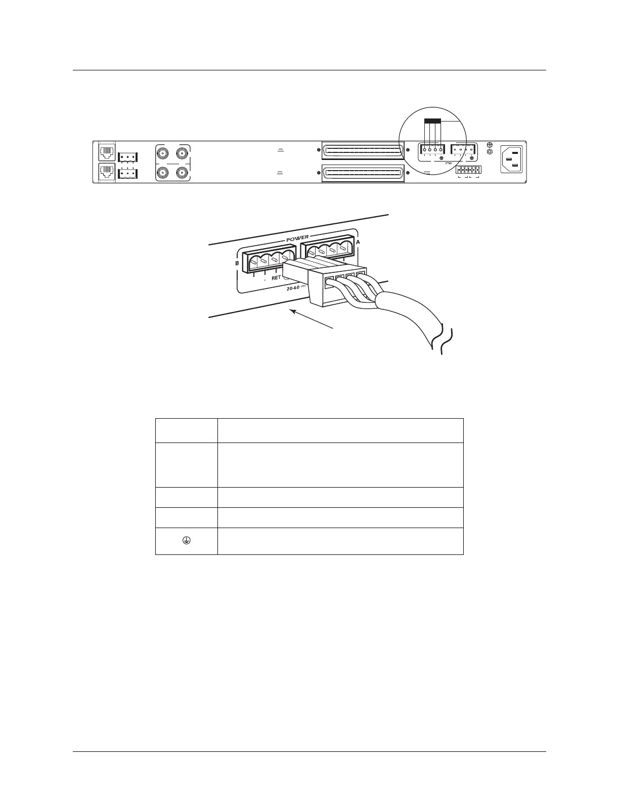
Figure 2-1. DC Power Connector
The following UL requirements must be met during installation of the MX2800 DC version:
1. Disconnect all power sources prior to servicing. Unit may use multiple power sources.
2. Voltage input requirement for DC version is Minimum –48 VDC, 0.8 amps
3. Voltage input requirement for AC version is Minimum 120 VAC, 0.32 amps
4. Connect to a reliably grounded –48 VDC source which is electrically isolated from the AC source. Use
24 VDC source for 1202289L3.
5. The branch circuit overcurrent protection must be a fuse or circuit breaker rated minimum 48 VDC,
maximum 20 amps.
Table 2-1. DC Connector Symbol Definitions
Symbol Definition
PWR FAIL
Battery backup connector. If the AC fails, a trap is sent to
as notification when connected to the 4175043L2 battery
backup or equivalent system.
–
Negative side of DC power source (usually –48 VDC)
RET
Positive side of DC power source (usually ground)
Frame Ground
DC POWER
115 AC 50/60Hz
0.8A
PWR
FAIL
RET
TRST R
CLK
A
CLK
B
S
–
L
A
N
NONCRITICAL
DSX-1/E1
(OUT)
DSX-1/E1
(IN)
NO COM NC
CRITICAL
M
O
D
E
M
OUT IN
A
B
A
-48V 0.7A
B
DS3/STS-1
PWR
FAIL
RET
–
PWR
FAI
L
USE COPPER
CONDUCT ORS ONLY!