2-6 61204659L1-1A
Section 2, Installation and Operation MX2800 STS-1 User Manual
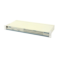
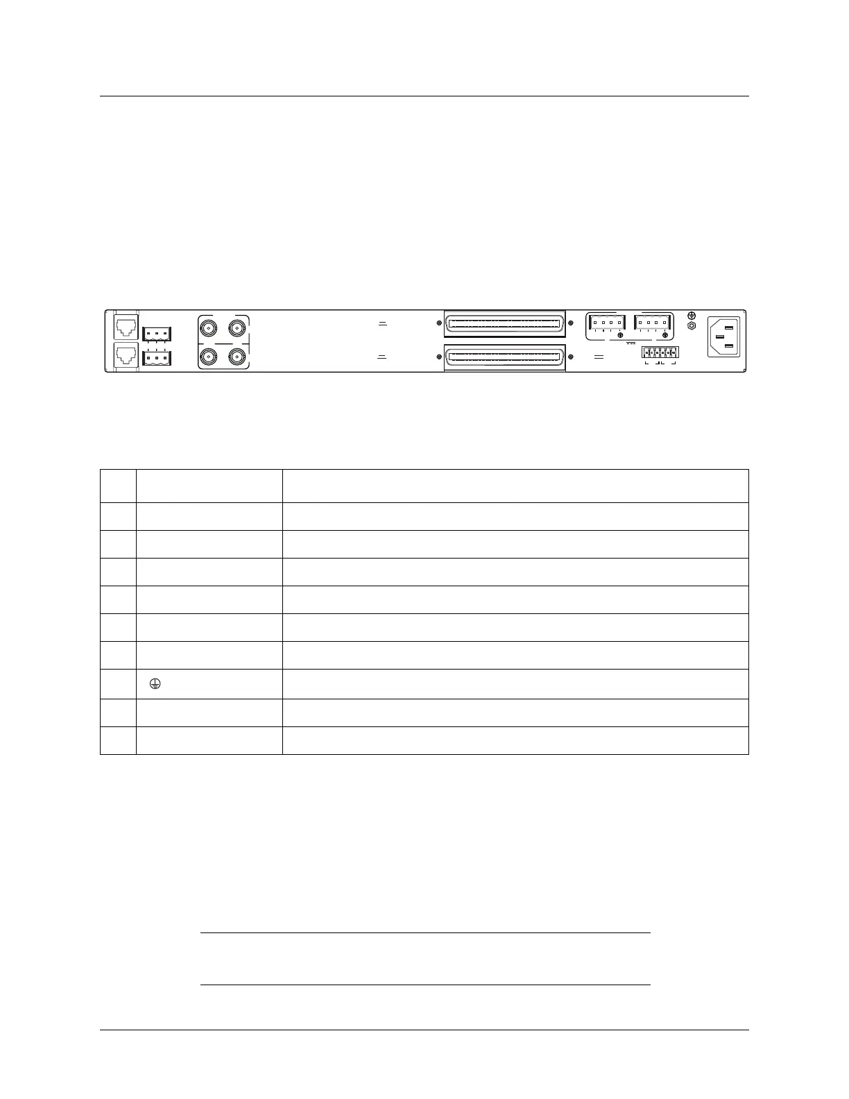
Rear Panel
• Two sets of NET in/out jacks
• Two amphenol connectors
• DC/AC power connections
• Wire-wrap pins for external connection of BITS clock
Descriptions for the items shown in Figure 2-3 are explained in Table 2-2. Pin assignments are given in
the tables in Appendix B, Pinouts.
Figure 2-3. MX2800 STS-1 Rear View
LAN Port
The LAN port is an 8-pin modular connector that provides a 10Base-T ethernet LAN interface. This LAN
interface is used for SNMP and Telnet control.
NOTE
Connect the LAN port to intra-building wiring only.
Table 2-2. MX2800 Review View Identifiers
# Item Function
1 Ethernet LAN 10Base-T Ethernet connection
2 Modem Telephone line connection for internal V.34
3 Noncritical/Critical Connections for external audible/visual alarms
4 DS3/STS-1 EC-1/STS-1 service connection for controller cards A and B
5 DSX-1/E1 64-pin female amphenol connectors for T1/E1s
6 Power DC power connection
7 Ground stud
8 115 VAC 50/60 Hz AC power connection
9 BITS Clock Wire-wrap pins for external connection of BITS clocks
DC POWER
115 AC 50/60Hz
0.8A
PWR
FAIL
RET
TRS T R
CLK
A
CLK
B
S
–
L
A
N
NONCRITICAL
DSX-1/E1
(OUT)
DSX-1/E1
(IN)
NO COM NC
CRITICAL
M
O
D
E
M
OUT IN
A
B
A
-48V 0.7A
B
DS3/STS-1
PWR
FAI L
RET
–
1
2
3
4
5
6
7
8
9
USE COPPER
CONDUCTORS ONLY!