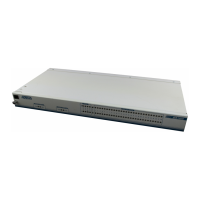
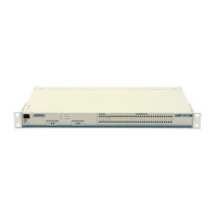
Chapter 2. Installation and Operation
61200290L1-1 MX2800 User Manual 2-5
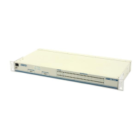
2. Install the mounting flanges on each side of the MX2800 at one
of the three available positions.
3. After the flanges have been installed, position the MX2800 at
the correct location within the rack and secure the mounting
flanges to the mounting rails of the rack.
4. Make all network, DTE, and power connections to the rear of
the unit. See Power Up on page 2-2 for more information on
making the DC power connection.
5. Using the 8-position modular to DB-9 female connector and the
8-position modular to 8-position modular cable, connect a
VT 100 terminal device to the
CRAFT port on the front panel of
the unit.
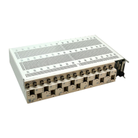
Connecting the Breakout Panel
The optional breakout panel (P/N 1200291L1) connects to the
MX2800 via the
IN and OUT Champ connectors and provides 28 RJ
connectors for the individual T1s/E1s. Shipment includes two six-
foot, 64-pin to 64-pin Amp cables which allow direct cabling to the
MX2800. Connect the breakout panel’s
IN Champ connector to the
MX2800’s
IN Champ connector and the breakout panel’s OUT
Champ connector to the MX2800’s
OUT Champ connector (see
Figure 2-2).
Be sure to install the flanges with the screws provided.
Two MX2800s may be stacked with no spacing between units. ADTRAN
recommends 1U (1.75") of separation above and below the two stacked
units. This spacing allows the unit to dissipate heat. The design of the
MX2800 uses the chassis to distribute heat generated by the unit's
internal cards. This design allows the unit to operate without a cooling
fan, which increases the overall reliability of the unit.