Chapter 7. Circuit and Network Redundancy
61200290L1-1 MX2800 User Manual 7-5
CIRCUIT AND NETWORK FAILURE RECOVERY MODE
In this mode, two controller cards are installed and connected to
two individual DS3 lines. This is, of course, the most complete
mode of redundancy. In this mode, the primary controller card is
connected to the primary DS3 line and the secondary controller
card is connected to the secondary DS3 line. The primary card and
line actively transmit data, while the other card and line stand by
ready to take over if the first fails. For example if Card A fails, then
control switches to Card B and DS3 B.
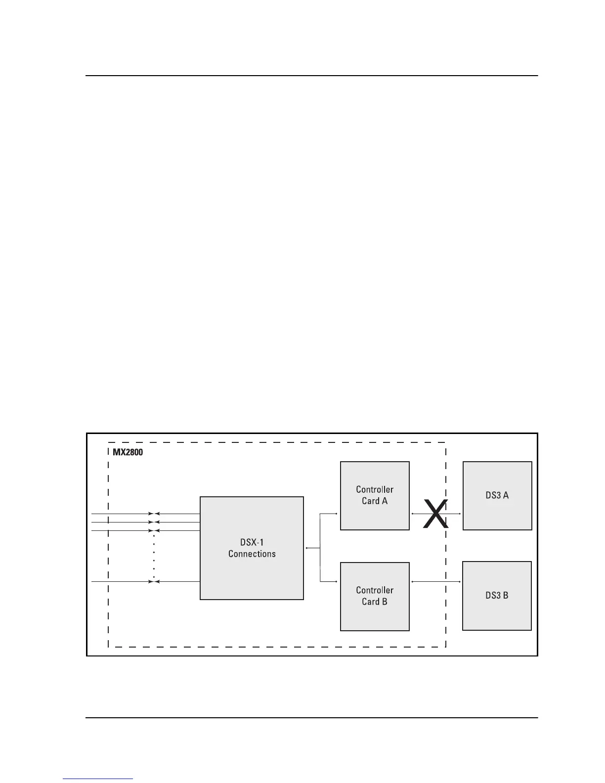
An important feature of the MX2800 is its ability to internally re-
route the network connection if a controller card and the opposite
network connection fail. For example, in the illustration given in
Figure 7-3, failed
DS3 A
is connected to healthy
C
ARD
A
; and
healthy
DS3 B
is connected to failed
C
ARD
B
. In a case like this, the
MX2800 is able to automatically re-route
DS3 B
to
C
ARD
A
.
The configuration requirements for this mode are the same as the
ones given for Circuit Failure Recovery Mode (see Table 7-1 on
page 7-4) except for the
N
ETWORK
P
ROTECTION
setting, which must
be set to
E
NABLE
.
Figure 7-3. Circuit and Network Failure Recovery Mode