7
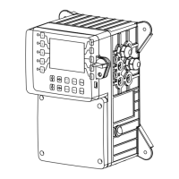
4-20mA Output Card Wiring
For isolated 4-20mA outputs an external power source for the loop must be supplied. JP4 and JP5 on the
board must be jumpered for isolated, with an external power source supplied to the external VDC input. The
external power source must not exceed 24 volts DC.
For non-isolated 4-20mA outputs the controller will supply the power for the loop. JP4 and JP5 must be
jumpered for non-isolated, and no connections are made to the external VDC points.
NOTE: The power for the mA output loop is always provided by the controller with either isolated or non-
NOTE: Older green versions of the 4 input cards supply +12 VDC and ground on the voltage terminals, and
isolated voltage.
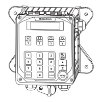
4-20mA Input Card Wiring
The 4-20mA input card requires that the external
device sending the 4-20mA input signal(s) supply
the power for the loop. The external power source
must not exceed 24 volts DC.
Auxiliary Flowmeter Input Card Wiring
signal and (-) ground connection. If the auxiliary
available on the card.
ISO
ISO
ISO
ISO
J5
J4
ISO
External
VDC Input
J8
J6
IN1+
V+
V+
V+
VEXT+
VEXT-
LED
IN1-
IN2+
IN2-
IN3+
IN3-
IN4+
IN4-
4 and 8 mA
Output Card
IN 8+
IN 8-
IN 5+
IN 5-
IN 6+
IN 6-
IN 7+
IN 7-
Input Card
G
G
G
mA outputs are
supplied as non-
isolated. To be
isolated J4, J5, J6
and J8 must be set
as shown here.
If J4, J5, J6 and J8
are set for isolated
an external DC
voltage must be
connected to
power the mA
outputs.
When isolated the
DC voltage connec-
tions will have the
external supply
instead of the
controller’s internal
+12 VDC.
V+
V+
V+
G
VEXT+
VEXT-
O5+
O5-
O6+
O6-
O7+
O7-
O8+
O8-
LED
G
G
O4-
O4+
O1+
O1-
O2-
O2+
O3-
O3+
mA
Outputs
5-8
DC
Voltage
Terminals
mA
Inputs
1 - 4
mA
Outputs
1 - 4
mA
Inputs
5 -8
DC
Voltage
Terminals
IN1+
IN4+
IN4
IN5
-
IN5-
IN6-
+
IN6
+
+5
+5
IN7+
IN7
IN8
-
IN8-
IN9-
+
IN9
+
IN10 -
IN10
+
LED
IN1-
IN2+
IN2-
IN3+
IN3-
+5
+5
Auxiliary Flowmeter
Input Card
Ground
Signal
VDC
VDC
VDC
VDC