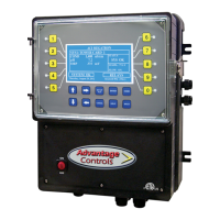
The MegaTron Controller is a microprocessor-based device designed to provide a wide range of control functions for recirculating water treatment systems. It is programmed via a front panel keypad and can be configured to offer a customized control system for various applications, including cooling tower and boiler systems. The unit's specific functions are determined by its model number, which can be cross-referenced with the Model Numbering Table.
Function Description:
The MegaTron controller can manage one or two separate systems, such as cooling towers or boilers, with various features depending on the model number. Each individual system can be configured with a variety of control functions:
- Conductivity Control (Bleed): Monitors and controls Total Dissolved Solids (TDS) in recirculating systems (cooling towers or boilers) in terms of electrical conductivity (MicroSiemens/cm). Units with make-up conductivity functionality can control tower TDS by calculating the difference between incoming make-up water and system conductivity.
- pH Control: Monitors and controls pH on a scale of 0-14 pH units.
- ORP Control: Monitors and controls ORP on a scale of +/- 1000 mV.
- Temperature Control: Included in base system control functions.
- Chemical Feed Timers (F1 to F5): Automate the addition of various chemicals by activating a relay output. Multiple timers can be supplied, each with a relay output, and can be programmed as one of the following types:
- Pulse Time: Activated by pulses from a make-up water meter (supplied separately). Accumulates 1-99 pulses to activate the timer for 0-99 minutes (in minutes and seconds).
- Feed with Bleed: Activates the relay output simultaneously with the bleed cycle, limiting the duration to prevent chemical overfeed.
- Feed after Bleed: Activates the relay output based on a user-defined percentage of the bleed-off time, running after a bleed cycle for the set percentage.
- Percentage: The relay is on for a programmable percentage of a continuously repeating cycle time.
- 28 Day: Based on a 28-day cycle with two independent programmable feed cycles, including prebleed and bleed lockout settings.
- Flow Switch Assembly (E): Included in base system control functions.
- Drum Level Alarm Inputs (L1 to L5): Included in base system control functions.
Optional Features:
- Conduit connections (A)
- Dry Contact relays (D)
- Remote Communications bus only (H)
- Direct Connect Communications (H1)
- Internet Connect Communications (H2)
- Additional System Card bus only (J)
- Additional Control Relays (K)
- ETL Agency Listing / Approvals (Y)
Important Technical Specifications:
- Power Supply: Internal regulated fused power supply, operates off 90 to 250 VAC at 47 to 63 Hz.
- Relay Outputs: Each output relay is individually protected with a replaceable fuse and will equal incoming line voltage.
- Electrode Specifications (Cooling Tower):
- Standard probes/flow assembly constructed of schedule 80 PVC with ¼” slip fittings.
- Sample line flow rate: 3-10 gpm.
- pH electrodes should be mounted vertically.
- O-ring sealed electrodes.
- Water temperature range: 32°F to 140°F.
- Maximum pressure: 150 psi.
- Electrode Specifications (Boiler):
- Standard boiler electrodes (BE-4BC) have a 1" MNPT stainless steel bushing and a 1”FNPT cross for mounting in the skimmer (surface) blowdown line.
- Electrode cross mounted on a 1"skimmer blowdown line within 4' of the boiler.
- Maximum water temperature: 400°F.
- Maximum pressure: 300 psi.
- A flow-throttling device is required downstream from the probe (within 12-24 inches) to prevent steam flashing.
- Temperature Compensation: Probes are temperature compensated for increased accuracy. An accurate temperature reading is critical for conductivity readings, with a compensation factor of approximately 1% per degree F.
Usage Features:
- Operating Modes: The controller has two modes:
- RUN Mode: For normal operation, displays system parameters. Alarms will flash if present. No settings can be entered or changed. Readings are updated every 6 seconds.
- SET-UP Mode: Used to make adjustments to settings and readings. Accessed by pressing the SETUP/RUN key from the RUN screen.
- Front Panel Keypad: Allows for easy navigation and programming.
- NUMBER Keys: Enter new values in SET UP mode and access sub-menus.
- UP/DOWN Keys: Cycle through text options.
- LEFT/RIGHT Keys: Cycle through text or setting options.
- SET UP/RUN Key: Switches between RUN and SET UP modes, accesses HOME menu.
- ENTER Key: Logs changed values.
- HOME Key: Returns to the HOME menu page.
- CANCEL Key: Clears keyed-in values.
- HELP Key: Accesses help screens.
- BACK Key: Returns to the last viewed menu screen.
- Menu Navigation: Menus are easily navigated by selecting the desired menu using the associated number key. Pop-up windows prompt for values or selections.
- Calibration: Factory calibrated for temperature, conductivity, pH, and ORP. Users can verify and adjust these settings.
- Conductivity Calibration: Remove electrode, wipe clean, reinstall, allow to stabilize, then enter corrected value. A "RESET ZERO" option is available when the probe is dry and out of solution.
- pH and ORP Calibration: Can be done with 1-point or 2-point calibration using known buffer solutions. Probes must be rinsed between buffers, and there should be at least 2 full pH points (e.g., 4 and 10) or 200 ORP points between buffer solutions.
- Customization: Users can define on-screen names for the unit, System 1, System 2 (if applicable), and each relay.
- Alarms: Displays any current alarms.
- Date and Time Set Up: Allows setting the date, time, day, and week.
- Configuration Menus: Access to set up passwords, relay activation, temperature scale, display contrast, flow switch, inputs, history time stamps, factory set-up, and system information.
- Passwords: Admin password for all menus except factory set up; User password for HOME menus made available in USER SET UP.
- Relays: Configure which function (timer, conductivity, alarms, etc.) activates a particular relay.
- Network: For setting up remote WebAdvantage communications (covered in a separate manual).
- History: Onboard history for probe readings, relay activations, keypad activity, calibrations, and alarm logs for each system. Displays sample interval, days of history retention, sensor samples, and relay/alarm events.
- Water Meters: Shows water meter input records (totalizer) and defines contact value (100) and units of measure (gallons).
- Relays Status: Allows viewing accumulated relay ON times, forcing relays ON or OFF, or seeing which relay is on. Also allows resetting accumulated run time to zero.
Maintenance Features:
- Electrode Cleaning: The only required maintenance for normal operation is cleaning the electrode(s).
- Frequency: Initially clean frequently (e.g., after one week), then adjust schedule based on observed changes in readings before and after cleaning.
- Conductivity Electrode Cleaning:
- Record current reading.
- Turn off water flow, bleed pressure, remove electrode.
- Use a clean cloth and mild cleaning solution for loose dirt.
- For deposits/scale, use a mild acid solution or sandpaper (200 grit or finer) on a flat surface. Avoid touching carbon tips with fingers.
- Reinstall and calibrate. If calibration fails after cleaning, repeat or replace electrode.
- pH and ORP Electrode Cleaning:
- Remove electrode by turning counter-clockwise.
- Spray with water/detergent, use a soft brush.
- Visually inspect for damage.
- Calibrate.
- Replace PTFE tape and re-mount, avoiding cable torsion.
- For slow response/non-reproducible measurements: Clean pH bulb with high-quality detergent, methyl alcohol, or other solvent using a Q-tip. Rinse, retest. If erratic, soak in 0.1 Molar HCl for 5 minutes, rinse, then 0.1 Molar NaOH for 5 minutes, rinse, and finally pH 4 buffer for 10 minutes.
- ORP/REDOX electrode: May be gently abraded with 600-grade wet silicone carbide paper, jeweler's rouge, or very fine steel wool (after trying other cleaning methods).
Troubleshooting:
The manual provides a troubleshooting chart for common issues:
- False reading: Possible cause: Bad/dirty electrode, out of calibration. Solution: Clean as needed, calibrate unit.
- Will not calibrate: Possible cause: Dirty electrode, faulty electrode, faulty wiring to electrode. Solution: Clean electrode, replace electrode if needed.
- No system power: Possible cause: Check power source, check fuse, check connections. Solution: Plug into different receptacle, replace as needed, ensure ribbon cables are secure.
- Pulse timer not activating: Possible cause: Check wiring, check external device. Solution: Repair as needed, repair/replace as needed.
- Outputs not energized: Possible cause: No flow, check fuse. Solution: Check sample line for clogged pipes/strainers, replace as needed.
Warranty and Service:
- Product Warranty: Advantage Controls, Inc. warrants control systems for 24 months from installation date against defects in material or workmanship. Liability is limited to repair or replacement of defective parts. Removal and installation costs are not covered.
- 30 Day Billing Memo Policy: A factory exchange program ensures minimum downtime. If a controller malfunctions, call technical support. If the problem cannot be solved over the phone, a warranted replacement panel is shipped within 48 hours on a 30 Day Billing Memo. The replacement panel is billed at list price less any applicable resale discount. Credit is issued upon return of the old panel (100% if in warranty, 50% if out of warranty). This covers only the panel, not electrodes or enclosure.
- FCC Warning: The equipment generates and uses radio frequency energy. Improper installation may cause interference to radio communications. It complies with FCC Rules for a class A computing device. In residential areas, the user may need to take measures to correct interference.