MK Series Portable Chiller : Air-Cooled : HE INSTRUMENT
Page: 19
ADVANTAGE ENGINEERING, INC.
525 East Stop 18 Road Greenwood, Indiana 46142
317-887-0729 Fax: 317-881-1277
Service Department Fax: 317-885-8683
Email: service@AdvantageEngineering.com
3.2 START UP / OPERATION PROCEDURE
A. SYSTEM FILL
1. The unit has an internal reservoir which must be filled and
maintained for proper operation. The unit has a level switch
mounted at the proper water level in the reservoir.
2. WATER QUALITY CONTROL. Lack of, as well as, improper
water treatment can damage the chilling unit. The services
of competent water treatment specialist should be
obtained and their recommendations followed. It is the
equipment owner’s responsibility to prevent damage from
foreign material or inadequate water treatment. See water
treatment section in section 8 of this manual for more
information.
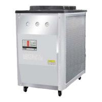
3. FOR AUTOMATIC FILL:
engage the water supply to
unit. The level switch will
activate the make-up
solenoid (figure 3.2A),
which will open and the
water supply will fill the
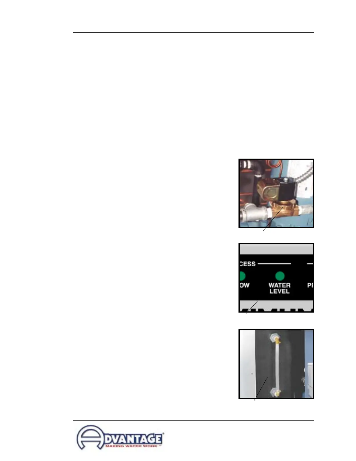
reservoir tank. The WATER
LEVEL light (figure 3.2B) on
the instrument will flash red
while the make-up solenoid
valve is open. When the
reservoir tank is filled, the
WATER LEVEL light will
illuminate green. During
operations, with the water
supply source “on”, the unit
will automatically maintain
the correct reservoir level.
4. MANUAL FILL: disconnect
the electrical power supply
and remove all necessary
cover panels to access the
reservoir. Add fluid directly
to the reservoir. When the
pump is first started, as
process lines are filled and
air is purged, additional fluid
may be required to restore
the reservoir to the correct
level as indicated by a
flashing red RESERVOIR
LEVEL light. During
operations, when the
Figure 3.2AMake-up solenoid valve
Figure 3.2B
Water level light - LE instruments
Figure 3.2C
Typical reservoir sight glass