Home
Advantage Engineering
Chiller
Maximum
Page 73
Advantage Engineering Maximum - Page 73
80 pages
Manual
Save Page as PDF
To Next Page
To Next Page
To Previous Page
To Previous Page
Loading...
MK Series Portable Chiller : Air-Cooled : HE INSTRUMENT
Page: 73
ADV
ANTAGE ENGINEERING, INC.
525 East Stop 18 Road Greenwood, Indiana 46142
317-887-0729 Fax: 317-881-1277
Service Department Fax: 317-885-8683
Email: service@AdvantageEngineering.com
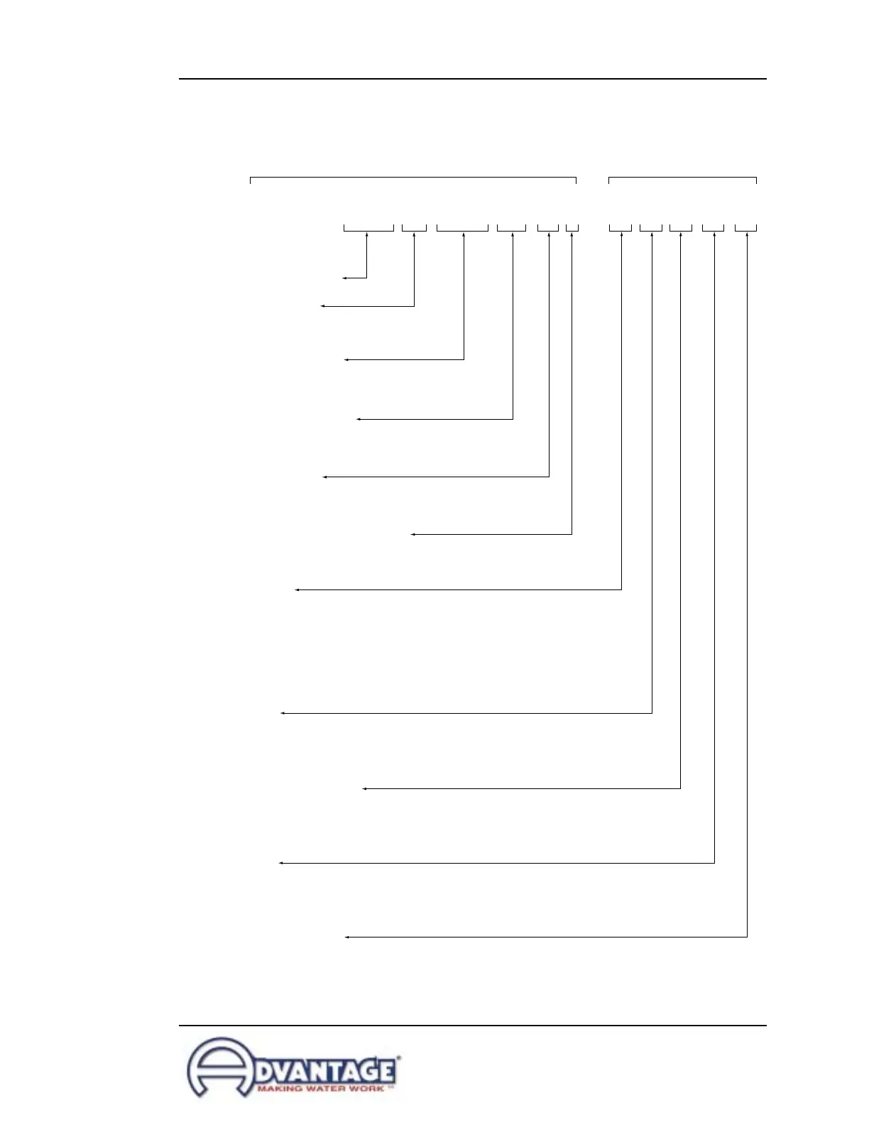
MK-10APTMRJ-41HBX
MODEL #
SUFFIX
COMPRESSOR HP
CONDENSING
A = Air
W = Water
TANK AND PUMP
PT = remote tank/pump
None = internal tank/pump
INSTRUMENTATION
None = 'LE' instrument
M = 'HE' instrument
FLOW DESIGN
R = Reverse flow
None= Direct flow
ELECTRICAL CONSTRUCTION
J = Nema 12
None = Nema 1
PUMPS
1 = one pump
2 = two pumps
3 = special
COMPRESSOR STYLE
H = Hermetic
S = Semi-hermetic
D = Discus
OTHER
B = Blower
F = Fan
R = Regulator valve
SPECIAL OPTIONS
Consult factory for more information
VOLTAGE
1 = 110/1/60
2 = 208-230/3/60
3 = 380/3/60
4 = 460/3/60
5 = 575/3/60
6 = 415/3/60
8.2
SPECIFICA
TIONS
72
74
Table of Contents
Main Page
Default Chapter
4
Table of Contents
4
1 General
7
Introduction
7
Efficiency
7
Safety
7
Clean Air Act
7
Miscellaneous
7
2 Installation
11
General
11
To and from Process Connections
11
Water Supply Connection
11
Air Cooled Condenser
11
Electrical Connection
11
3 Operations
17
General
17
Start Up/Operations Procedure
17
Instrument/Operation
17
Shut down Procedure
17
4 Troubleshooting
39
Sensors
39
Process/Evaporator Pump
39
Compressor
39
Low Flow
39
High Pressure
39
Low Pressure
39
Water Level
39
Freezestat
42
Oil Pressure
42
Crankcase Heater
42
Electronics
43
5 Maintenance
45
Warranty Service Procedure
45
Periodic Preventative Maintenance
45
Special Maintenance
45
Solenoid Valve Service
45
Pump Seal Service
45
Checking the Refrigerant Charge
45
Proper Cleaning Procedure for Brazed Plate Evaporators
53
DIP Switch Adjustment
55
Display / Keyboard Operation
57
East Stop 18 Road Greenwood, Indiana
59
6 Components
59
Water System Refrigeration System
59
Refrigeration System
60
7 Related Drawings
63
Mechanical Schematic - 15 / 20 /25
63
Duct Schematic for Air Cooled Chillers
63
Mechanical Schematic - 5 / 7.5 / 10 Ton Models
64
Mechanical Schematic - 15 / 20 / 25 / 30 Ton Models
65
Physical - 5 Ton Models
66
Physical - 7.5 / 10 Ton Models
67
Electrical
70
8 Appendix
71
Specifications
71
Model # and Suffix Coding
71
Operations below 48°F
71
Water Quality Control
71
Inhibited Propylene Glycol
71
Sensor Current Vs Temperature
76
Pressure-Temperature Chart for R-22 Refrigerant
77
Chiller Capacity and Derate Chart
78