1.2 Installation and Cabling
1.2.1 Installing the Speed Dome
Steps:
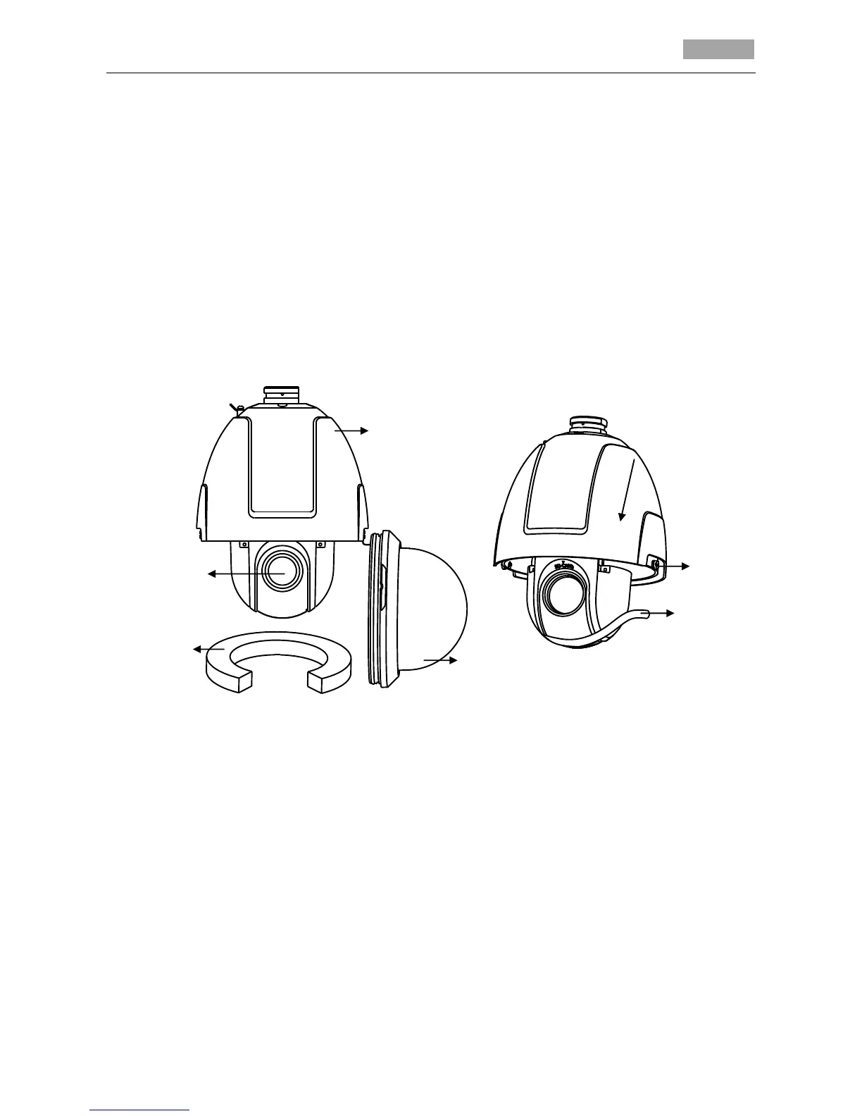
1. Loosen the two lock screws on both sides of the speed dome. Pull the lower dome to separate it
from the back box as shown in Figure 1-3.
Note: Please do not remove the lock screws from the dome.
2. Remove the protective foam, sticker and lens cover from the dome drive.
3. Align the slots on the lower dome with the lock screws on the back box to reinstall the lower
dome. Tighten the lock screws.
Figure 1-3 Remove the Lower Dome
4. Install the dome mount. Please refer to the related sections in Chapter 2 and Chapter 3 for
specific installation methods with different mounts.
Notes:
For cement wall, you need to use the expansion screws to fix the mount. The mounting hole of
the expansion pipe on the wall should align with the mounting hole on the mount.
For wooden wall, you can just use the self-tapping screw to fix the mount.
Please make sure that the wall is strong enough to withstand more than 8 times the weight of
the dome and the mount.
5. Configure the dome address, baud rate, protocol and other parameters through DIP switch SW1
and SW2 which you can see after removing the lower dome. Please refer to Section 1.3 DIP
Switch Settings for details.
Notes:
 Loading...