EN
36
737.096 | 11.37
Alternative data cable
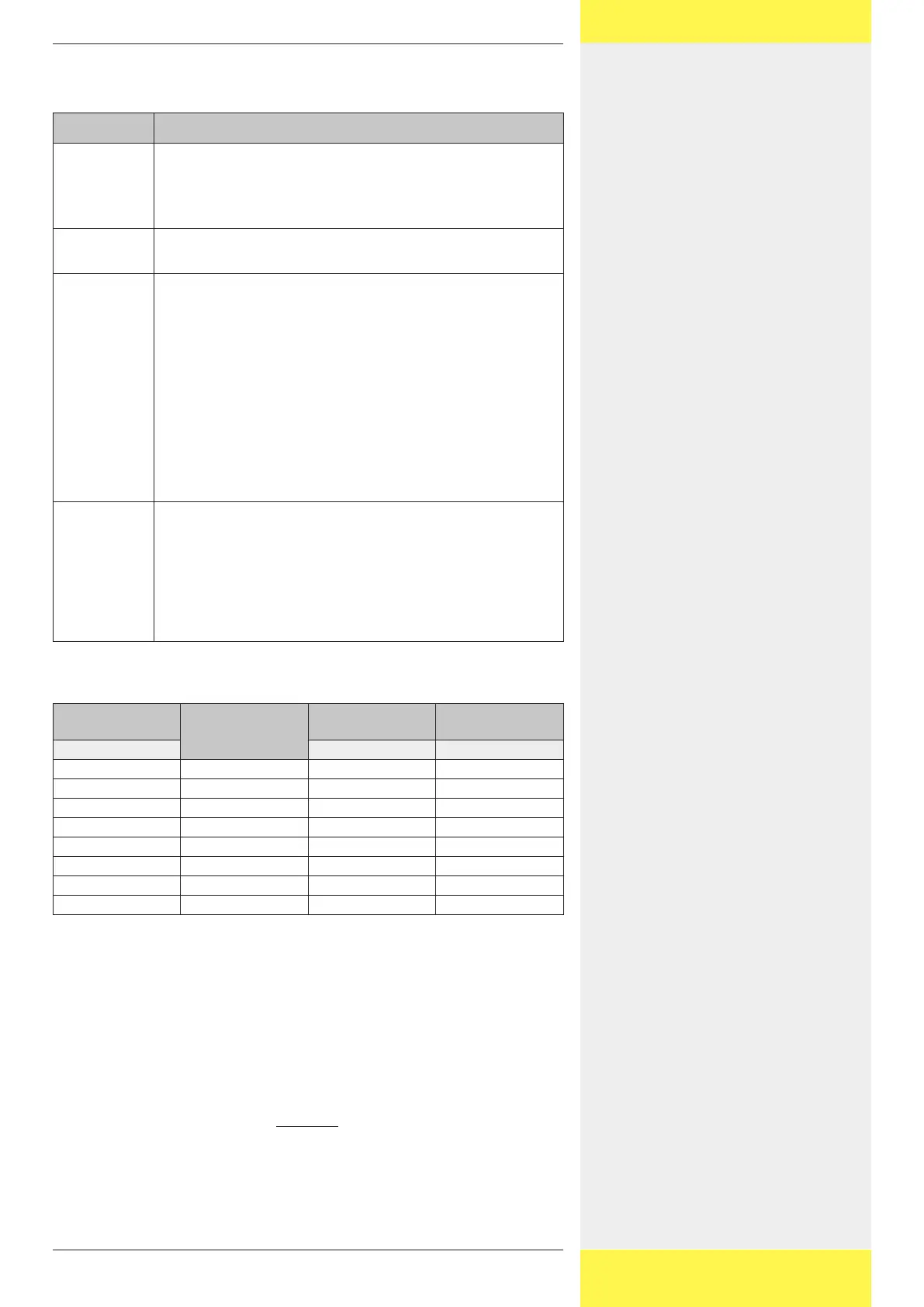
The following table describes the properties of the alternative data cable.
Property Description
Application Data connection between:
• Inverter and inverter
• StecaGrid Vision and inverter
• External data logger and inverter
Cable Type Cat-5, total length ≤ 200 m (from the StecaGrid Vision or
external data logger to the last inverter)
Plugs StecaGrid Vision:
• The StecaGrid Vision is supplied with the following plugs:
– HARTING PushPull RJ45 10G, No. 09 45 145 1560 (push-
pull locking mechanism, can be wired without tools,
IP65).
– COMBICON 3-pole
• When using a standard RJ45 plug, remove the plastic collar
from the RJ45 socket on the StecaGrid Vision.
External data loggers:
• Solar-Log: standard RJ45
• Other: Use a plug according to the manufacturer's
specifications.
Connecor pin
assignments
• StecaGrid Vision to inverter:
– with RJ45: 1:1
– with COMBICON: see following table
• Inverter to inverter 1:1
• Solar-Log to inverter: see following table
• Other external data logger to inverter: Connector pin as-
signments according to the manufacturer's specifications
Connector pin assignments for inverter to StecaGrid Vision / Solar-
Log
Inverter
RJ45
Signal
StecaGrid Vision
COMBICON
Solar-Log
RJ45
Contact Contact Contact
1 Data A 1 1
2 Data B 2 4
3 – – 2
4 – – 8
5 – – 5
6 – – 6
7 – – 7
8 Ground 3 3
3.4.3 Termination
To avoid data transmission errors the start and end of the data connection be-
tween the inverters and the StecaGrid Vision / data logger must be terminated
with a termination resistor as described below:
• The StecaGrid Vision at the start of the data connection is permanently termi-
nated internally.
• The external data logger must be terminated according to the manufacturer’s
specifications.
• The last inverter (at the end of the data connection) must be terminated
at the interface card. The termination can be switched on and off via a DIP
switch; see the figure in chapter Adressing.