Do you have a question about the AEI DK-9880 Series and is the answer not in the manual?
Combines digital access keypad, door alarm, and door chime for security applications.
High security system using a remote keypad and master decoder unit communicating digitally.
Details power input, DC output, common ground, and data bus terminals.
Includes forced open, open-too-long, and auto re-lock alarms.
Features egress input for exit and duress output for security alerts.
Describes Output 1, 2, and 3 relay or transistor capabilities.
Explains factory-set master code and default values for initial setup.
Overview of installer and user programming access keys, codes, and validation.
Details selection, factory settings, and limitations for user code modes.
Guides for setting Single User or Multi-User mode and refreshing the system.
Step-by-step example of setting and operating the system in Single User Mode.
Step-by-step example of setting and operating the system in Multi-User Mode.
Diagram and instructions for connecting multiple remote keypads to the master unit.
Procedure for removing user access in Multi-User mode.
Describes the tamper switch and its alarm activation upon unit separation.
Details operation voltage, current drain, code combinations, and dimensions.
Illustrates common uses for Output 1, 2, and 3 connections.
Explains terms like Dry Contact, N.C., N.O., and Open Collector Output.
The DK-9680 / DK-9880 Super is a versatile security keypad system that integrates digital access control, door alarm, and door chime functions into a single unit. Designed for both office and home security installations, it prioritizes high security through a "Split Decoded" design. This architecture divides the system into a remote keypad unit and a master decoder unit, which communicate using digital codes. This design prevents unauthorized access even if the connection wires between the units are cut or shorted, as it bypasses the keypad function to activate controlled devices.
The system utilizes current mode data bus communication, requiring only two wires for connection. A single master unit can support up to three remote keypad units connected in parallel, each operating independently. Both DK-9680 and DK-9880 remote keypads are fully compatible and can be mixed within a multi-station setup.
The DK-9680 / DK-9880 Super offers two application software options: Single User Code and Multi-User Codes. The Single User Code mode provides 10,000 possible combinations, while the Multi-User Codes mode offers over 100 million combinations, enhancing security.
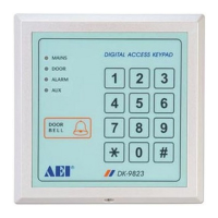
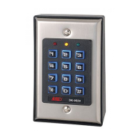
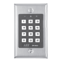
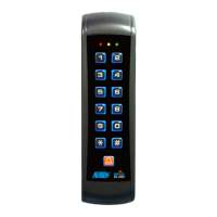
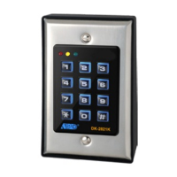
The DK-9680 keypad unit is weatherproof, making it suitable for both outdoor and indoor installations. The DK-9880 keypad unit features a slim design, allowing it to blend seamlessly with various residential and office decors. Both systems are available in versions A, B, and C, which share identical specifications except for their output facilities.
Door Sensing: The system incorporates a Normally Closed (N.C.) input circuit that monitors the door controlled by Output 1, typically with a magnetic contact. When the door is opened, the circuit becomes open, triggering several functions:
Egress Input: A Normally Open (N.O.) input terminal connects to Common Ground (-) via a momentary push-button switch to activate Output 1. This allows users inside the protected premises to exit without entering a code, bypassing security. This terminal should be left open if not used.
Duress Output: An NPN transistor open collector output switches to ground (-) when a Duress Code is entered. This output can be connected to an alarm control panel or telephone dialer. The output transistor has a maximum sink current of 100mA and a maximum Vce of 12V DC.
Programming Modes: The system offers both Single User and Multi-User modes. The factory default is Multi-User Mode with a Master Code of "0000." Users can switch between modes and refresh the system, which resets all programmed data except the Master Code to default values.
Single User Code Mode: This mode allows one 4-digit user code per output. Users simply enter the 4-digit code to activate the specific output without needing to press the '#' key.
Multi-User Codes Mode: This mode supports groups of user codes (4 to 8 digits) for each output. Users must press the '#' key to confirm code entry and activate the desired output. Group 1 supports up to 100 users for Output 1, while Groups 2 and 3 support up to 10 users each for Output 2 and Output 3, respectively.
Code Entry Limitation for Multi-User Codes: To prevent conflicts with the Duress function, the first digit of a "Saved" User code "+2" or "-2" is not allowed for subsequent User Code entries.
Accelerated Code: For Start/Stop mode, outputs can be activated by entering only the first two digits of the User Code. Deactivating requires the complete User Code.
DAP Jumper (Direct Access to Programming): If the Personal Master Code is forgotten, the DAP jumper can be used to override the forgotten code and permit direct entry into programming mode. The procedure involves disconnecting power, moving the DAP jumper from OFF to ON, reconnecting power (speaker beeps), moving the jumper back to OFF (beeps stop), and then entering new data.
Keyboard Illumination LED (DK-9680) / Key LED (DK-9880): The LED lights up for 10 seconds when a key button is pressed, indicating the allowable time for each digit in code entry. If the LED is off, the digit entry is invalid.
Visible and Audible Indicators: The remote keypad features a built-in buzzer (or speaker at the master unit) and an amber LED to provide tones and signals for operation status, including programming mode, successful/unsuccessful key/code entry, DAP jumper status, and standby mode.
Tamper Switch: Each remote keypad unit includes a tamper switch. If the keypad unit is separated from its mounting box, the switch releases, sending an alarm command to the Master unit for 60 seconds. The alarm can be stopped by entering User Code 1 before the alarm time expires.
Re-program the Keypad with New Data: Users can change existing data, such as User Codes or Door Open timing, at any time by entering programming mode with their Personal Master Code and then inputting new data for specific access keys. After programming, exiting the mode saves all new data and returns the keypad to normal operation.
Delete User (Multi-User Mode): To delete a user who no longer has access, enter programming mode with the Personal Master Code, then enter the User Number followed by the '#' key for the specific output group (e.g., 105# for User 05 from output 1). Exit programming mode to save changes.
| IP Rating | IP65 |
|---|---|
| Power Source | 5V DC |
| Operating Temperature | -10°C to +50°C |
| Storage Temperature | -20°C to +60°C |
| Keys | 16 keys |