Do you have a question about the AEI DK-2822 and is the answer not in the manual?
Details the key features of the DK-2822, including Tri-Tech design, software generation, and outputs.
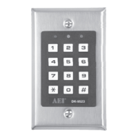
Lists the items included in the DK-2822 package, such as the keypad, EM cards, screws, and manual.
Details optional decoders for split-decoded operation, such as DA-2800 and DA-2801.
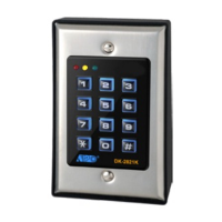
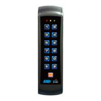
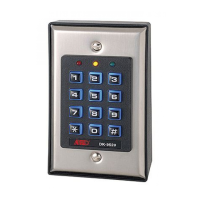
Lists auxiliary readers and keypads for multi-station operation, including AR-2802, AR-2806, AR-2807, AR-2809.
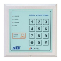
Diagram showing the assembly of the DK-2822 keypad and its components.
Important precautions to prevent interference and accidental short circuits during installation.
Details the Normally Closed tamper switch contact for alarm system integration.
Describes the 12V DC power input terminals and common ground points.
Specifies the positive 12V power supply terminal for the electric lock.
Explains the negative power supply terminal for the electric lock strike.
Describes the bi-directional data communication port for connecting auxiliary devices.
Details the Normally Open egress input terminal for door opening functions.
Explains the Output 2 relay contacts (NC, NO, Common) for auxiliary controls.
Describes the NPN transistor open collector output for version 'B' keypads.
Details the Normally Open relay contact for the door bell function on version 'B'.
Describes the open collector output for Keypad Active or Alarm notifications.
Explains the open collector output for duress alarm notification.
Identifies the common ground terminal for the keypad system.
Details the N.C. input for monitoring door position status for various functions.
Describes the N.O. input for controlling Output 1 inhibition, useful for inter-lock systems.
Explains the open collector output for inter-lock control between keypads.
Explains the status indications provided by the Red/Green and Amber LEDs.
Describes the tones and LED signals used by the keypad for system status.
Explains the jumper settings for controlling the keypad's back-lit illumination.
Defines the criteria and rules for prime codes, prime cards, and secondary user codes.
Details the 5 operation media levels for configuring security settings.
Suggests a format for listing user information for programming convenience and tracking.
Explains the keypad's power-up delay and how to stop it.
Details how to enter programming mode using the Master Code.
Provides steps to access programming mode using the DAP code (2828).
Explains how to refresh the system to default values using the Refreshing Code (9999).
Explains how to pause daily inhibition of Output 1 using the Super User Code.
Explains how to manually inhibit all User Codes and EM Cards for Output 1.
Step-by-step guide for programming and operating the keypad with EM Card only.
Step-by-step guide for programming and operating the keypad with Private User Code only.
Guide for programming and operating with EM Card plus Secondary User Code.
Guide for programming and operating with EM Card plus Common User Code.
Instructions for deleting user codes or EM cards from memory.
How to clear all users from a selected group.
Demonstrates reporting a duress event when using an EM Card.
Explains how to report duress events when using EM Cards with Duress Codes.
Explains how to manually reset output timers using the Super User Code.
Explains how to manually pause the real-time inhibition using the Super User Code.
Describes how the Super User Code overrides inhibition for door access.
Provides examples of scenarios where an intelligent egress button is beneficial.
Explains how to set egress delay timing (0 to 99 seconds).
Configures Wiegand data output modes (Disabled, Mode A, Mode B, Mode C).
Explains the Wiegand data output format options for EM cards and user codes.
Details the 26-bit Wiegand data protocol and format from EM cards.
Explains Wiegand data generation from user codes, including precautions.
Configures the keypad for stand-alone or server operation for system expansion.
Instructions on how to exit programming mode and return to normal operation.
Steps to enter programming mode using the factory default Master Code 0000.
Instructions to change the factory Master Code to a personal one for security.
Example for programming an EM Card to operate Output 1.
Example for programming a User Code to operate Output 1.
Example for programming EM Card with User Code for Output 1.
Example for programming EM Card with Common User Code for Output 1.
Instructions on closing programming mode and returning to normal operation.
Diagram and description of the 6-pin wire harness for Wiegand output.
Details the timing and electrical characteristics of Wiegand data transmission.
Explains the programmable Wiegand data output formats: 26-bit, 34-bit, and 37-bit.
Example showing a standalone door lock setup with the DK-2822 keypad.
Example of setting up an inter-lock system with two DK-2822 keypads.
Lists and shows connections for optional auxiliary readers and keypads.
Shows connection diagrams for optional DA-2800 and DA-2801 split-decoders.
Explains the tamper switch connection for alarm system integration.
Details how door sensors enable functions like auto-re-lock, alarms, and inter-lock.
Explains how to use the alarm output for forced open or egress delay alarms.
Explains the Key Active output for notifications like LEDs or buzzers when a key is touched.
Details the Duress Output for notifying guards or alarm systems when duress code is entered.
Details using Output 2 for shunting N.C. zones or alarm system arm-disarm control.
Explains the function and equivalence of transistor open collector outputs.