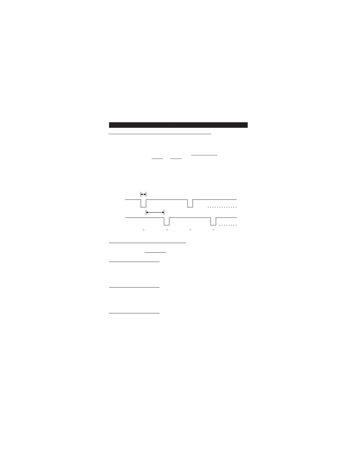
The Timing and Electrical Manner of The Wiegand Data Output
Wiegand is a common medium in the communication between readers and controller in access
control. The Wiegand data from the keypad unit provides a level of compatibility for readers and
controller that can be used by consultants in custom project development.
The Wiegand interface uses three wires, one of which is a Common Ground and two of which are
data transmission wires called DATA 0 and DATA 1. When no data is being sent both DATA 0 and
DATA 1 are at high voltage. When a “0” is sent the DATA 0 is at low voltage while the DATA 1 stays
at a high voltage. When a “1” is sent DATA 1 is at the low voltage while DATA 0 stays at the high
voltage.
The high voltage level in the keypad unit is +5VDC to accommodate for long cable runs
(approximate 500 feet) from it to the associated controller typically located in a secure closet.
50 uS pulse
Data 0 Line
2 mS pulse interval
Data 1 Line
0 1 0 1
+5V
0V
+5V
0V
Wiegand Data 26-Bit, 34-Bit or 37-Bit Selection
The Wiegand data output is programmable to 26-bit, 34-bit or 37-bit standard format for EM
Cards and user codes on LOCATION 93.
1) 26-Bit Wiegand Data Output
Bit 1 : Even Parity Bit (bit 2 – bit 13)
Bit 2 – Bit 25 : 24 Bit ID Number
Bit 26 : Odd Parity Bit (bit 14 – bit 25)
2) 34-Bit Wiegand Data Output
Bit 1 : Even Parity Bit (bit 2 – bit 17)
Bit 2 – Bit 33 : 32 Bit ID Number
Bit 34 : Odd Parity Bit (bit 18 – bit 33)
3) 37-Bit Wiegand Data Output
Bit 1 : Even Parity Bit (bit 2 – bit 19)
Bit 2 – Bit 36 : 35 Bit ID Number
Bit 37 : Odd Parity Bit (bit 19 – bit 36)
WIEGAND OUTPUT FORMATS
50