INTRODUCTION
CONNECTIONTERMINALS
DK-9680/DK-9880Superisthecombinationofdigitalaccesskeypad,dooralarmanddoorchimeinonesystem.
Itisanidealsystemfordoorstrikeandotheraccesscontrolapplicationsinofficeandhomesecurityinstallations .
Thesystemadopts"SplitDecoded"designphilosophytogivethehighestsecurity.Eachkeypadissplitintotwo
parts,theremotekeypadunitandthemasterdecoderunit.Theycommunicatewitheachotherindigitalcodes.
Anyonewhotriestocutorshorttheconnectionwiresbetweenthetwounitscannotspoilthehighsecurityofthe
systemorbypassthekeypadfunctio ntoactivatethecontrolleddevices.TheDK-9680/DK-9880Superuses
currentmodedatabuscommunication,onlytwowiresarerequired,onemasterunitcanaccommodateupto3
remotekeypadunitsconnectedinparallelfortotallyindependentoperation.TheremotekeypadsofDK-9680and
DK-9880arefullycompatiblewitheachotherandtheycanbemixedusewithonemasterunitinmultistation
operation.
TheDK-9680/DK-9880Superconsiststwosetsofapplicationsoftwareforowner'sselection.TheyareSingleUser
CodeandMulti-UserCodesforeachoutput.Thesingleusercodegives10,00 0combinationsandthemulti-user
codesgiveover100millioncombinations.
Theweatherproof,whichissuitableforbothout-doorandin-doorinstallations.
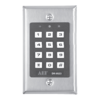
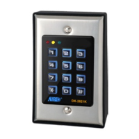
ThekeypadunitoftheDK-9880Superisslim,whichblendssmoothlyintoanyresidentialandofficedecors.Both
keypadsystemsareavailablewithversionA,BandC.Theyhaveidenticalspecificationsexcepttheiroutputs
facilities.
Powersupplyinput,12VACorDCpoweris
possible,Nopolaritydiscriminationforthe
terminalsisrequired.
12VoutputpowerfortheDCoperateddoor
latch.Outputcurrent2Ampmaximum.
Thecommong roundingpointofthekeypad
system.
Thisisthecommunicationdatabusofthe
masterunitandtheremotekeypadunit(s).Itis
alsothepowersupplylinefortheremote
keypadunit(s).ConnectittotheDATAterminal
attheremotekeypadunit(s).
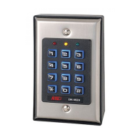
keypadunitoftheDK-9680Superis
THEMASTERUNIT
!
!
!
!
POWERINAC/DC
DCOUTPUT(+)
COMMONGROUND(-)
DATA
PRODUCT
OUTPUT
OUTPUT1OUTPUT2OUTPUT3
DK-9680A/DK-9880A
DK-9680B/DK-9880B
DK-9680C/DK-9880C
5AmpRelay1AmpRelay1AmpRelay
5AmpRelay1AmpRelayNPNTransistorOpenCollector
5AmpRelayNPNTransistorOpenCollectorNPNTransistorOpenCollector
DK-9680
DK-9880
SUPER
SPLIT-DECODEDSECURITYKEYPAD
THREE-OUTPUTSYSTEMWITHDOORALARM
FORDOORSTRIKEANDSECURITYCONTROLAPPLICATIONS
1
!
!
!
!
!
DOORSENSING
:
:
:
:
NOTE:
EGRESSINPUT
DURESSOUTPUT
OUTPUT1
OUTPUT2
:
:
ANormallyClosed(N.C.)inputcircuitreferstoground.With
thehelpofamagneticcontact(e.g.AEIMC-01orMC-02)
tomonitorthedoorwhichiscontrolledbyoutput1.The
circuitisopenwhenthedoorisopen.Itinitiatesthe
followingfunctions:
1)WhenthedoorisFORCED
OPEN--thedoorisopenedwithouttheuseofavalid
codeortheEGRESSbutton,thedoorforcedopenalarm
(built-in)willbeactivefor60seconds.
2)WhenthedoorisLEFTOPEN
longerthanthepre-setallowabledooropentime,the
dooropen-too-longalarmwillbeactivecontinuouslyuntil
thedoorisclosedagain.
3)Whenthed oorisopenedandthen
re-closed,thekeypadwillreleasetheelectriclatch
immediatelytore-lockthedoorbeforetheendofthe
operationtimeinmomentarymode,oryoudonotrequire
toenterCode1againtore-lockthedoorinStart/Stop
mode.
4)Eachtimewhenthedoorisopened,
thedoorchimeactivatesfor2seconds.
1)TheabovefunctionsareavailableforOutput1
only.Pleasesee"PROGRAMMING"toenable
thedesiredfunctions.
2)ConnectthisterminaltoCommonGround(-)if
doorsensingswitchisnotused.
ANormallyOpen(N.O.)inputterminalrefersto(-)ground.ConnectittoCommonGro und(-)viaamomentary
push-buttonswitchtoactivateOutput1.Allowsusertobypassthesecuritycode1bypushingthepush-button
switch.Thisswitchisnormallyputinsidetheprotectedpremisesnearthedoortoallowthoseinsidethe
protectedpremisestoexitwithoutkeyinginthecode.
Leavethisterminalopenifitisnotused.
AnNPNtransistoropencollectoroutput.Itswitchestoground(-)whentheDuressCodeisentered.Connectto
activateanalarmcontrolpanelortelephonedialer.
Outputtransistorrating:Icmax--100mAsink,Vcemax--12VDC
(VersionA,BC)
5Amprelaydryconta cts,withNormallyOpen(N.O.)andNormallyClosed(N.C.)terminals.Thisrelayis
primarilypreparedfordoorstrikeapplication,orforothersecurityandaccesscontrols.Fordoorstrike
connection,usetheN.O.contactforFail-securedoorlock;andusetheN.C.contactforFail-safedoorlock.If
forothersecurityandaccesscontrolapplications,pleaseconsultthemanualofyoursystemfortheappropriate
pairofterminals(N.C.orN.O.)fortheconnection.Therelayoutputisprogrammableformomentaryor
start/stopoperation.
Output2ispreparedforothersecurityandaccessc ontrolapplications.Theoutputisprogrammablefor
momentaryorstart/stopoperation.VersionABuserelayoutput,andtheVersionCusestransistoroutput.
1Amprelaydrycontacts,withN.O.andN.C.outputterminals.
AnNPNtransistoropencollectoroutput.Itswitchestoground(-)whenCode2isentered
(activates).Transistorratings:Icmax--100mAsink,Vcemax--12VDC
DoorForcedOpenAlarm
DoorOpen-too-longAlarm
DoorAutoRe-lock
VisitorAnnouncer
VersionA&B
VersionC
&
&
DK-9680C/DK-9880CMASTERUNIT
OUTPUT3:OPENCOLLECTOR
OUTPUT2:1ARELAY
OUTPUT1:5ARELAY
OUTPUT3:OPENCOLLECTOR
OUTPUT2:OPENCOLLECTOR
OUTPUT1:5ARELAY
OTHERCONNECTIONSSAMEASDK-9680A/DK-9880A
OTHERCONNECTIONSSAMEASDK-9680A/DK-9880A
DK-9680B/DK-9880BMASTERUNIT
2