Do you have a question about the AEM 30-3508 and is the answer not in the manual?
Provides a general description of the adapter kit and compatible models.
Guidance on initial setup and accessing essential information.
Information on obtaining configuration files and manuals from the website.
Lists optional accessories available for purchase.
Details specific considerations for using the Infinity 508 with the harness.
Explains the Molex MX123 sealed connection system used by the EMS.
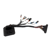
Describes the adapter harness and its integrated connectors for plug-and-play installation.
Explains how the Infinity EMS drives the vehicle's dashboard gauges and CEL.
Step-by-step instructions for installing the Infinity EMS in the vehicle.
Comprehensive table detailing Infinity EMS pin assignments and Honda wiring equivalents.
Pinout configuration for the auxiliary Deutsch connector.
Details various connector pinouts including Lambda 1, AEM Net, and Flash Enable.
Visual guide to Honda ECU connector pin numbering.
Visual guide to Infinity EMS connector pin numbering.
Outlines the terms and conditions of the product warranty.
This document serves as an instruction manual for the AEM Performance Electronics Plug & Play Adapter Harness, part number 30-3508, designed for 2000-2005 Honda S2000 models. This adapter harness is compatible with both Infinity-6 and Infinity-8h* EMS systems.
The AEM Infinity Adapter Kit 30-3508 is a true standalone system that facilitates the connection between an AEM Infinity Engine Management System (EMS) and the factory wiring harness of a 2000-2005 Honda S2000. This "plug and play" design eliminates the need for cutting or splicing wires, simplifying the installation process. It supports all 2.0L (AP1) engines and early 2.2L (AP2) engines equipped with a cable-driven throttle body. The system takes over the functions of the factory ECU, driving essential dashboard components such as the tachometer, coolant temperature gauge, and the Check Engine Light (CEL).
The CEL, rather than being used for OBD2 diagnostics, is dedicated to the AEM "MILOutput" feature, which activates if any of several inputs (air temp, baro pressure, coolant temp, exhaust back pressure, fuel pressure, UEGO #1, UEGO #2, MAF analog, MAF digital, MAP, oil pressure, or throttle position) are in an error state. Unused sensors should be turned OFF in the Wizard to prevent false readings.
The adapter harness integrates several connectors for expanded functionality. A gray Deutsch 6P DTM "Lambda #1" connector is provided for connecting a UEGO wideband Bosch LSU4.2 sensor (AEM 30-2001) via an extension harness (AEM 30-3600). A gray Deutsch 4P DTM connector is used for "AEMNet," an open architecture based on CAN 2.0, enabling communication between multiple enabled devices like dashboards and data loggers. A black Delphi 2-pin "Flash Enable" connector is included for secondary hardware flashing, typically used only for initial flashing, with subsequent upgrades handled via software. Additionally, a gray Deutsch 12P DTM "Auxiliary" connector allows for easy adaptation of various ancillary inputs and outputs.
The installation process begins by recording the Honda CD Player activation code and radio presets, then disconnecting the vehicle battery. The stock ECU is located on the left-side kick panel and is accessed by removing the door sill and kick panel cover. The three ECU connectors are unplugged by depressing their "thumb" locks, taking care to avoid stressing the wires. The ECU is then removed by unscrewing two M6 mounting bolts.
The AEM Infinity EMS is secured using an adhesive hook and loop (Velcro) strip and one of the OEM ECU bolts. One side of the Velcro is attached to the back of the EMS and the other to the chassis. The OEM ECU bolt is loosely screwed into a spare boss. The AEM 80-pin connector is then attached to the EMS, secured by sliding the red locking tab. The EMS is positioned so the adapter harness contours around the kick panel area, and the OEM ECU bolt's washer locks onto the EMS mounting tab, after which the bolt is tightened.
The three OEM Honda ECU connectors are then connected to the Honda header on the AEM adapter. The included mini USB communication cable is connected to the EMS. If AEMnet devices are to be daisy-chained, they are secured to the AEM adapter's 4P Deutsch connector.
For wideband UEGO sensor installation, the vehicle should be on a lift or jack stands. A bung is welded, or an existing O2 sensor bung is used, pre-catalytic converter, for optimal accuracy. The UEGO sensor is installed using a 7/8" wrench. The UEGO extension harness (sold separately) is routed into the cockpit through the factory grommet on the left side firewall (RHD vehicles may differ). A small slit is cut in the grommet to pass the Deutsch connector, which is then reattached to the firewall and mated to the Deutsch connector on the AEM adapter.
After all auxiliary connections are made, the battery is reconnected, and the system is connected to the Infinity Tuner software for verification. Once all components are verified, the kick panel and door sill are reinstalled.
The AEM Infinity EMS is designed for total flexibility in engine tuning, but it requires an experienced tuner. Misuse or improper tuning can damage the engine. Users who are not well-versed in engine dynamics or engine management systems are advised to refer installation to an AEM-trained tuning shop or contact AEM technical assistance.
All supplied AEM calibrations, Wizards, and tuning information are provided as starting points only. It is the engine tuner's responsibility to confirm the calibration's safety for its intended use. AEM disclaims responsibility for engine damage resulting from misuse or mistuning.
The manual includes detailed pinout information for the Infinity EMS, including dedicated, assigned, available, not applicable, and required functions for each pin, along with notes on their specifications and usage. This information is crucial for advanced tuning and troubleshooting. The AUX Connector Pinout and Miscellaneous Pinouts for LAMBDA 1, AEMNet, and FLASH ENABLE are also provided, detailing Deutsch pin, Infinity pin, wire color, pin name, and default pin function. Honda pin numbering and Infinity pin numbering diagrams are included to aid in correct identification and connection.
For any electronic product issues, users must contact the AEM EMS tech line before requesting a Return Merchandise Authorization (RMA), as most problems can be resolved over the phone. Improper use, installation, abuse, unauthorized repairs, or alterations will void the warranty. UEGO oxygen sensors are considered wear items and are not covered under warranty.
| Product Type | Wideband Air/Fuel Ratio Sensor |
|---|---|
| Part Number | 30-3508 |
| Brand | AEM |
| Power Supply | 10-18V DC |
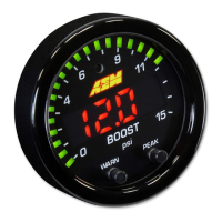
| Gauge Size | 52mm |
| Display | Digital LED |
| Compatible Vehicle Type | Universal |
| Maximum Voltage Output | 5V |
| Connector Type | Weatherproof Connector |
| Housing Material | Aluminum |
| Sensor Type | Wideband |
| Output Type | Analog |
| Operating Temperature | 0°C to 75°C |
| AFR Range | 10:1 to 20:1 |
| Output | 0-5V |