2000–2005 Honda S2000
9
© 2017 AEM Performance Electronics
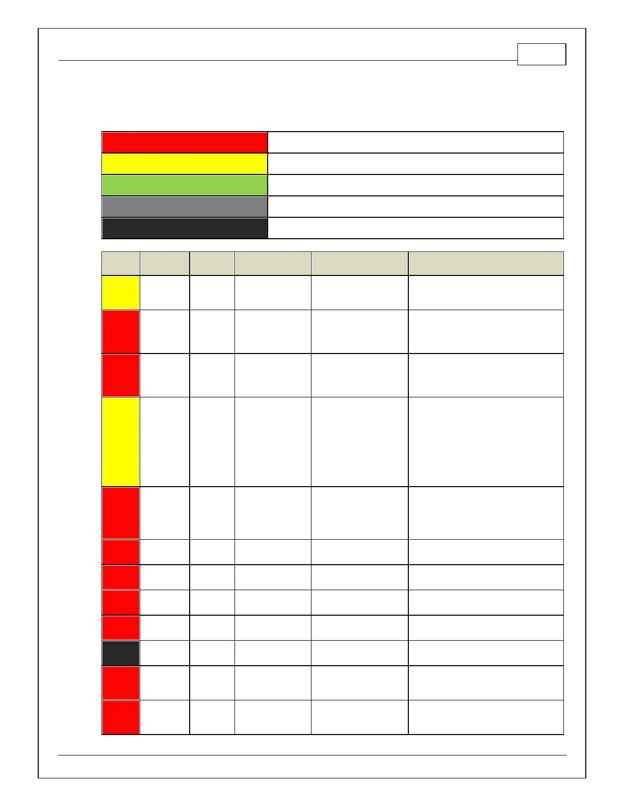
PINOUTS
Infinity Pinout
Dedicated and not reconfigurable
Assigned but reconfigurable
Not used in this configuration
Required for proper function
Infinity Hardware
Specification
Lowside switch, 4A max, No
internal f ly back diode.
See Setup Wizard Page "LowSide Assignment
Tables" for output assignment and 2D table
"LS4_Duty [%]" f or on/off activation.
Lowside switch, 4A max
with internal flyback diode.
Inductiv e load should NOT
have f ull time power.
The tachometer is pre-calibrated using a
combination of the LS5_Freq [Hz] 1-axis table
and the LS5_Duty [%] 2-axis table.
Lowside switch, 4A max
with internal flyback diode.
Inductiv e load should NOT
have f ull time power.
The coolant temp gauge is pre-calibrated using
the LS6_Freq [Hz] 1-axis table and the
LS6_Duty [%] 2-axis table. This signal is
pulled up to 5V.
Malfunction Indicator
Light
Lowside switch, 4A max, No
internal f ly back diode.
See Wizard page "LowSide Assignment
Tables" for output assignment and 2D table
"LS3_Duty [%]" f or activ ation. MIL Activ ates
when any of the f ollowing f lags are true:
ErrorAirTemp, ErrorBaro, ErrorCoolantTemp,
ErrorEBP, ErrorFuelPressure,
UEGO_0_Diag_error, UEGO_1_Diag_error,
ErrorMAFAnalog, ErrorMAFDigital, ErrorMAP,
ErrorOilPressure, ErrorThrottle.
Lowside switch f or UEGO heater control.
Connect to pin 4 of Bosch UEGO sensor.
NOTE that pin 3 of the Sensor is heater (+)
and must be power by a fused/switched 12V
supply .
Trim Current signal. Connect to pin 2 of
Bosch UEGO sensor
Pumping Current signal. Connect to pin 6 of
Bosch UEGO sensor
Nernst Voltage signal. Connect to pin 1 of
Bosch UEGO sensor
Virtual Ground signal. Connect to pin 5 of
Bosch UEGO sensor.
Dedicated power
management CPU
Full time battery power. MUST be powered
before the ignition switch input is triggered.
0–5V f alling edge fire. Do NOT connect
directly to coil primary . Must use an ignitor or
CDI that accepts a falling edge f ire signal.
0–5V f alling edge fire. Do NOT connect
directly to coil primary . Must use an ignitor or
CDI that accepts a falling edge f ire signal.
 Loading...