12
© 2017 AEM Performance Electronics
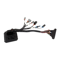
P/N 30-3508
Infinity Hardware
Specification
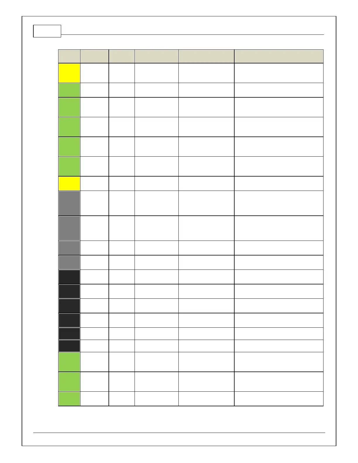
12 bit A/D, 100K pullup to
5V
0–5V analog signal. See the Manifold
Pressure in Setup Wizard f or setup and
calibration.
12 bit A/D, 100K pullup to
5V
0–5V analog signal found on the Auxiliary
Connector
Dif f erential Variable
Reluctance Zero Cross
Detection
See Driv en Wheel Speed Calibration in the
Setup Wizard Vehicle Speed page.
Dif f erential Variable
Reluctance Zero Cross
Detection
See Driv en Wheel Speed Calibration in the
Setup Wizard Vehicle Speed page.
Dif f erential Variable
Reluctance Zero Cross
Detection
See Non Driven Wheel Speed Calibration in
the Setup Wizard Vehicle Speed page.
Dif f erential Variable
Reluctance Zero Cross
Detection
See Non Driven Wheel Speed Calibration in
the Setup Wizard Vehicle Speed page.
0.7A max, High Side Solid
State Relay
+12V High Side Driv e. See Setup Wizard
Honda VTEC page for options.
Automotiv e, Programmable
Stepper Driv er, up to 28V
and ±1.4A
Be sure that each internal coil of the stepper
motor is properly paired with the 1A/1B and
2A/2B ECU outputs. Supports Bi-Polar stepper
motors only .
Automotiv e, Programmable
Stepper Driv er, up to 28V
and ±1.4A
Be sure that each internal coil of the stepper
motor is properly paired with the 1A/1B and
2A/2B ECU outputs. Supports Bi-Polar stepper
motors only .
5.0A max Throttle Control
Hbridge Driv e
2000–2005 S2000 do not use drive by wire
throttle.
5.0A max Throttle Control
Hbridge Driv e
2000–2005 S2000 do not use drive by wire
throttle.
12 v olt power from relay powers the Infinity,
Lambda sensor, and AEMNet
Saturated or peak and hold,
3A max continuous
Saturated or peak and hold,
3A max continuous
Saturated or peak and hold,
3A max continuous
Connects directly to ground
12 v olt power from relay powers the Infinity
12 bit A/D, 100K pullup to
5V
0–5V analog signal. Do not connect signals
referenced to +12V as this can permanently
damage the ECU.
12 bit A/D, 100K pullup to
5V
0–5V analog signal. Do not connect signals
referenced to +12V as this can permanently
damage the ECU.
12 bit A/D, 100K pullup to
5V
0–5V analog signal found on the Auxiliary
Connector
 Loading...