Connecting to Stand alone ECU’s
When connecting to a third party EFI system, the AEM UEGO gauge’s WHITE Analog
Output wire shall be connected to the analog O2 sensor input of that system. Consult
the documentation provided with the system for detailed instructions. (for AEM EMS see
page 4)
Serial Output (optional)
The serial output can be used for data logging when an EFI system is not accessible.
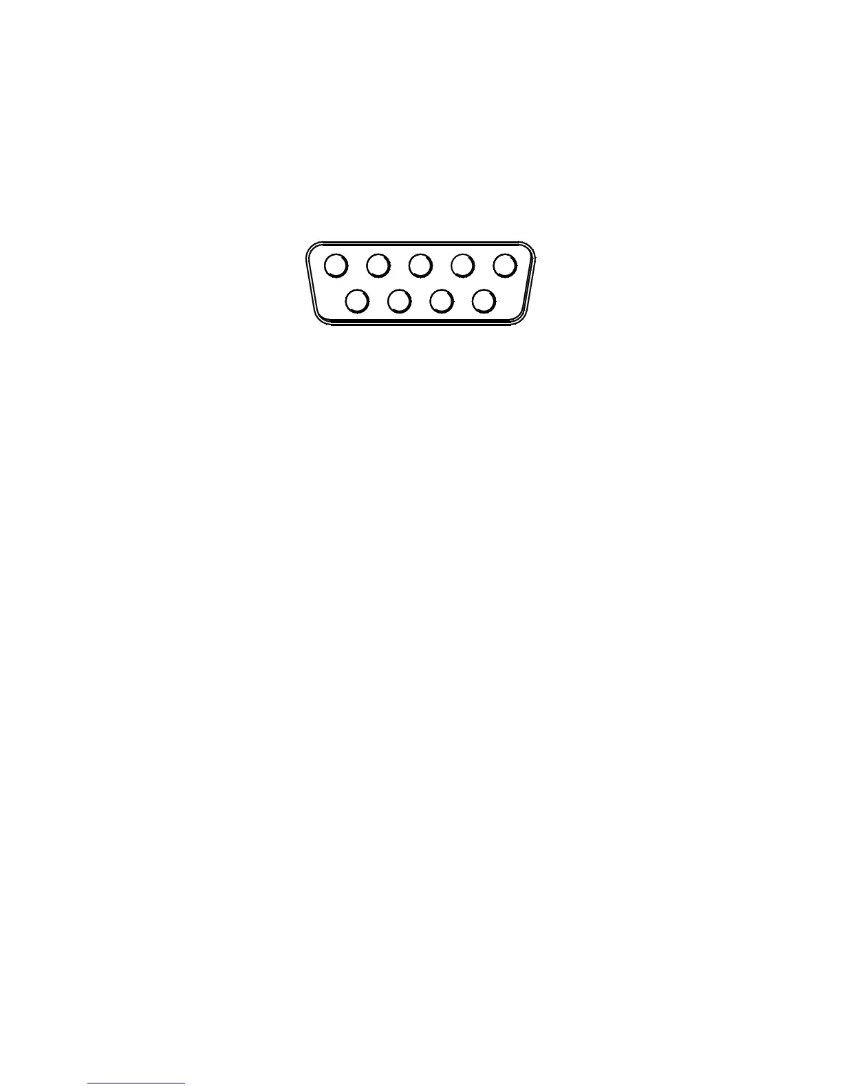
To run the data stream, a RS-232 (DB-9) Female Receptacle shall be purchased.
12345
6789
Wire View of RS-232 (DB-9) Male Plug
Two wires need to be connected to a RS-232 serial port. The BLUE wire from the AEM
UEGO Gauge shall be connected to Pin #2 (RX) on the serial port for receiving data.
Pin # 5 (GND) on the serial port shall be grounded. If a standard 9-pin serial cable is to
be cut instead, the (RX) wire is typically RED and the (GND) wire is typically GREEN.
However, this should be confirmed with a continuity tester before attempting.
Use HyperTerminal for testing the data stream. This software is found on most PCs. To
find HyperTerminal go to: Start | All Programs | Accessories | Communications |
HyperTerminal. Name the New Connection and click OK. Set the COM port to the one
being used and click OK.
Bits Per Second = 9600
Data Bits = 8
Parity = None
Stop Bits = 1
Flow Control = Hardware
Verify the settings above and click OK. When power is supplied to the AEM UEGO
Gauge, AFR (or Lambda) data will be displayed, as shown below.