This document outlines the installation, operation, and maintenance procedures for the Aerauliqa QRCE series ventilation unit with high-efficiency heat recovery.
Function Description
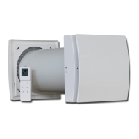
The QRCE series ventilation unit is designed for civil (non-residential) and commercial applications, facilitating room air renewal while minimizing primary energy consumption. It performs forced air renewal with heat recovery. The unit is suitable for environments free of aggressive, corrosive, and/or explosive agents. It can be integrated with traditional heating and cooling systems and can also operate autonomously with proper accessories.
The basic configuration of the unit comprises:
- Supply and Exhaust EC Fan: Ensures efficient air movement.
- High-Efficiency Air-to-Air Heat Recovery with Built-in Motorized By-pass Device: Maximizes energy efficiency by recovering heat from exhaust air and transferring it to fresh intake air. The by-pass device allows for direct air flow when heat recovery is not needed.
- Air Filters: Positioned close to the air inlet, with F7 class efficiency for fresh air and M5 class efficiency for return air, ensuring air quality.
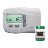
- Built-in Electric Box with Controller and Remote User Interface: Provides centralized control and monitoring capabilities.
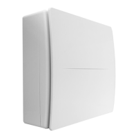
- Self-Supporting Panels: Form the structural enclosure of the unit.
Important Technical Specifications
The unit's working environment should have an air temperature not lower than -20°C and not higher than 45°C, with relative humidity not exceeding 95%.
Each unit is provided with an identification plate listing key specifications, including:
- Model and Serial Number: For identification.
- Date of Production and Code: Manufacturing details.
- Max Input Current [A] and Max Input Power [W]: For the basic unit and for possible electric heater.
- Power Supply [V-ph-Hz]: Electrical requirements.
- Nominal (Supply) Airflow Rate [m³/h]: Air handling capacity.
- External Static Pressure [Pa]: Pressure capability for the basic unit.
- Sound Power Level [dB(A)]: Noise emission.
- Operative Range: Air temperature and relative humidity limits.
Dimensions and Weights (Horizontal Version - examples for different models):
| Model |
L (mm) |
W (mm) |
H (mm) |
W1 (mm) |
X (mm) |
Y (mm) |
E (mm) |
F (mm) |
G (mm) |
D1 (mm) |
D2 (mm) |
L1 (mm) |
L2 (mm) |
Weight (basic units) (kg) |
Weight (CCS/CDX) (kg) |
Weight (PLM) (kg) |
| 500 |
1350 |
680 |
330 |
760 |
230 |
225 |
52.5 |
46 |
128 |
1/2" M |
3/4" M |
350 |
340 |
85 |
28/28 |
21 |
| 1000 |
1470 |
820 |
370 |
900 |
300 |
265 |
52.5 |
46 |
130 |
1/2" M |
3/4" M |
400 |
380 |
105 |
31/31 |
23 |
| 1500 |
1850 |
1030 |
455 |
1110 |
390 |
350 |
52.5 |
46 |
158 |
1/2" M |
3/4" M |
400 |
460 |
175 |
35/35 |
26 |
| 2000 |
1850 |
1460 |
455 |
1540 |
600 |
350 |
52.5 |
46 |
170 |
1/2" M |
3/4" M |
400 |
460 |
230 |
42/42 |
30 |
| 3000 |
2150 |
1460 |
590 |
1540 |
590 |
485 |
52.5 |
55 |
170 |
1/2" M |
1" M |
502 |
580 |
290 |
52/52 |
39 |
| 4000 |
2150 |
1840 |
590 |
1920 |
780 |
485 |
52.5 |
55 |
170 |
1/2" M |
1" M |
502 |
580 |
360 |
58/58 |
44 |
CDX Model ODS Connections [mm] (Liquid line/Gas line):
- 500: 8/8
- 1000-1500-2000: 12/16
- 3000: 16/22
- 4000: 22/28
Usage Features
Installation:
- Placement: The unit can be installed INSIDE or OUTSIDE (requiring a roof cover). It must be fixed to suitable supporting structures.
- Support Points: For horizontal units, M8 threaded bars with vibration dampers are used. For vertical units, supporting feet are fixed to the floor with an antivibration layer.
- Condensation Discharge: Position the unit where condensation discharge can occur easily, with a minimum 3° slope towards the discharge point. Each point requires a suitable drain trap, which must be filled with water before startup. The drain trap should include a tap for cleaning and allow easy disassembly.
- Air Duct Connections: Ducts must be correctly sized to match the unit's external static pressure. Insulated ducts are recommended to prevent condensation and reduce noise. Flexible joints should always be installed between the unit and air ducts, ensuring electrical continuity with a ground cable if metal ducts are used. Duct weight should not load the unit.
- Damper Installation (SKR1, SKR2): Dampers are provided with holes on their coupling flange, an adhesive perimetric gasket, and self-drilling screws. The gasket is applied around the flange perimeter, and the damper is fixed to the air intake/outlet, ensuring its shaft is accessible.
- Water Coil Connection (CCS): Uses GAS male threaded connections. Tightening must be done carefully to avoid damage. An air valve at the top and a water discharge valve at the bottom are required. Antifreeze should be used in very low air temperatures.
- Direct Expansion Coil Connections (CDX): Requires copper pipes suitable for R410A refrigeration, sized according to the provided table. Pipes must be clean and free from moisture. The freon coil is supplied with welded plugs and pressurized by nitrogen; these plugs should not be removed until connection to the refrigerant circuit.
- Electrical Connections: Must be carried out by qualified personnel. Main power supply must be switched off before any operation. All power lines must be properly protected. Voltage and frequency must match the unit's specifications. Adequate cabling is essential to support a voltage drop inferior to 3% of the nominal during startup. Adapters, multiple plugs, and extension leads should be avoided for the main power supply.
Handling and Storage:
- Packing: Units are supplied on a bench with cardboard packaging. Packaging should remain intact until installation. Stacking is limited to one similar or smaller unit on the ground unit.
- Handling: Use hand pallet trucks or forklift trucks for lifting. Avoid rotation without control. Check the unit's weight before moving. Handle with care to prevent damage to functional parts.
- Storage: If not immediately installed, store the unit in its package in a dry place, away from sun, rain, heat sources, sand, and wind. Do not stack units beyond the specified limit. Environment temperature range for storage: min -20°C to max +60°C.
Maintenance Features
General Maintenance Guidelines:
- Safety First: BEFORE SERVICING THE UNIT, SWITCH OFF THE MAIN POWER SUPPLY. All maintenance operations must be carried out by trained and qualified personnel. Hand and body protections are required.
- Documentation: It is recommended to maintain a machine book to track actions taken on the unit, including date, type of action, description, measurements, identified anomalies, and alarms.
Scheduled Monthly Check:
- Air Filters: Filters are located near air inlets and are accessible via hinged doors (horizontal units: lower hinged doors; vertical units: front hinged doors) or by removing end side panels. Filter elements are secured by a locking plate that needs to be turned 90° with a Phillips head screwdriver for removal and replacement. Filters are not cleanable and must be replaced when dirty. Optional filter pressure switches can provide automatic filter condition checks.
Scheduled Yearly Check:
- Electrical Devices: Check all electrical devices and connections for tightness.
- Mechanical and Water Connections: Check all mechanical and water connections.
- Heat Recovery: Perform a visual check of the heat exchange surface for cleanliness and integrity. This requires dismounting the panels for special access to filters.
- Fans: Access fans through hinged doors. Check for perfect cleaning and free rotation of the impeller.
Not Scheduled Maintenance:
- Fan Removal and Replacement: Access the fan section via the hinged door and unhook the fast plug. Use a 5 mm Allen key for unscrewing. Remove the fan stirrup (if present) and gradually loosen the screws of the fan locking devices to remove the fan. Reassemble in reverse order.
- By-pass Actuator Removal and Replacement: Remove the middle panel between the two end panels (and intermediate support for larger models). Unscrew internal screws fixing the by-pass device frame. Disconnect the 7-pole faston fast plug from the actuator. Loosen and remove the two screws holding the actuator, then lift it to free it from the blade shaft. Reassemble in reverse order, ensuring the 7-pole connector is correctly matched.
- Manual Reset of Internal Electric Heater(s): In case of overtemperature, a manual reset of the heater thermal protection may be needed. Two release buttons (one for horizontal, one for vertical unit) are located on the heater frame, accessible via the end filter panels. A screwdriver can be used to facilitate this.
- Electric Heater Replacement: Remove the middle panel, disconnect the heater, remove the closure element of the sliding guide, and remove the heater. Replace with a new one following the opposite sequence.
- Roof Cover Removal (QRCE Vertical Unit): For outdoor installations, access to upper panels requires preventive removal of the roof cover, which is fixed by M6 screws (requiring a 5 mm Allen key).
Troubleshooting:
A table provides possible solutions for common detected failures:
- Fans not running: Check power supply, electrical connections, thermal protection, and fan speed signal.
- Insufficient airflow: Check for dirty air filters, clogged air ducts, and fan signal/speed settings.
- Insufficient heating/cooling performance: Check temperature setpoint, heat transfer fluid rate/temperature, airflow, and defrost mode.
- Condensate discharge failed: Check for clogged discharge point or missing/unsuitable drain trap.
Material Disposal:
At the end of the unit's lifetime, components must be dismantled and disposed of according to local regulations. Main materials include precoated galvanized steel, galvanized steel, aluminum, copper, polyester, polyethylene, glass wool, and plastic. During disconnection, avoid gas leakage or liquid spillage. Units should be delivered to specialized centers for disposal.