HE-110 1B+ II Water Wizard Water Heaters
OMM-0063_0D Installation, Operation & Maintenance Manual
Page 6 of 50 11/28/2018
AERCO International, Inc. • 100 Oritani Dr. • Blauvelt, New York 10913
•
CHAPTER 2. GENERAL INFORMATION
This instruction covers the AERCO Helitherm Model B+ WATER WIZARD Steam to Water
Heat Exchangers. STEAM is the PRIMARY or TUBE SIDE FLUID. The WATER BEING
HEATED is the Heat Exchanger (service or domestic water or other fluid) is the SECONDARY
or SHELL SIDE FLUID.
2.1. MODEL NAMES
The number of coils in a particular Heat Exchanger is denoted by the two digits following the
“B+” in the Heat Exchanger Model Number. That is: B+03 = 3 coils, B=07 = 7 coils, B+11 = 11
coils, and B+15 = 15 coils.
The Style designation for a Heat Exchanger denotes materials of construction for the various
components of the assembly. If this information is required for a specific Heat Exchanger,
contact the nearest AERCO Sales Representative.
2.2. HEAT EXCHANGER CONFIGURATIONS
There are three basic heat exchanger configurations; those with a pneumatically controlled
valve (CXT-P), those with Electronic Control System (ECS) with an electronically controlled
valve (CXT-E), and a “bare” heat exchanger without controls or valve. See separate ECS
Controls manual, AC-105, for information about the Electronic controls System and
electronically operated CXT-E valve. See Section 3 for available accessories.
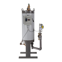
2.3. ACCESSORIES
Accessories included in the AERCO B+ Heater Package Assembly (See Figures 1a, 1b, 1c,
21, 22, and 23) include:
• Steam Flow Control Valve – either Air-Operated or Self-Contained as ordered and
furnished, sized as required for the service.
• Temperature Controller – installed in the Control Box when an Air Operated Control Valve is
furnished (See Fig. 20, Item 134).
• Over-Temperature Limit System, including the following:
• Temperature Switch – installed in the Control Box (Figure 20, Item 126).
• Solenoid Valves:
o Water – installed in the Heater Top Head.
o Air – installed in the Control Box when an Air Operated Control Valve is furnished
(Fig. 20, Item 135).
o Steam – installed on the Self-Contained Control Valve when such valve is furnished.
o Indicator Lights: “Power On” and “Tripped” – installed in the Control Box (Figure 20,
Items 129 and 130).
• Steam Compound Pressure Gage – mounted below the Control Box (Figure 20, Item 133).
• Shell Hot Water Outlet Temperature Gage – mounted below the Control Box (Figure 20,
Item 132).