FUSE
CONN1
+
-
FUSE
CONN1
+
-
230V
~
50Hz
1
2
3
4
5
6
9
8
7
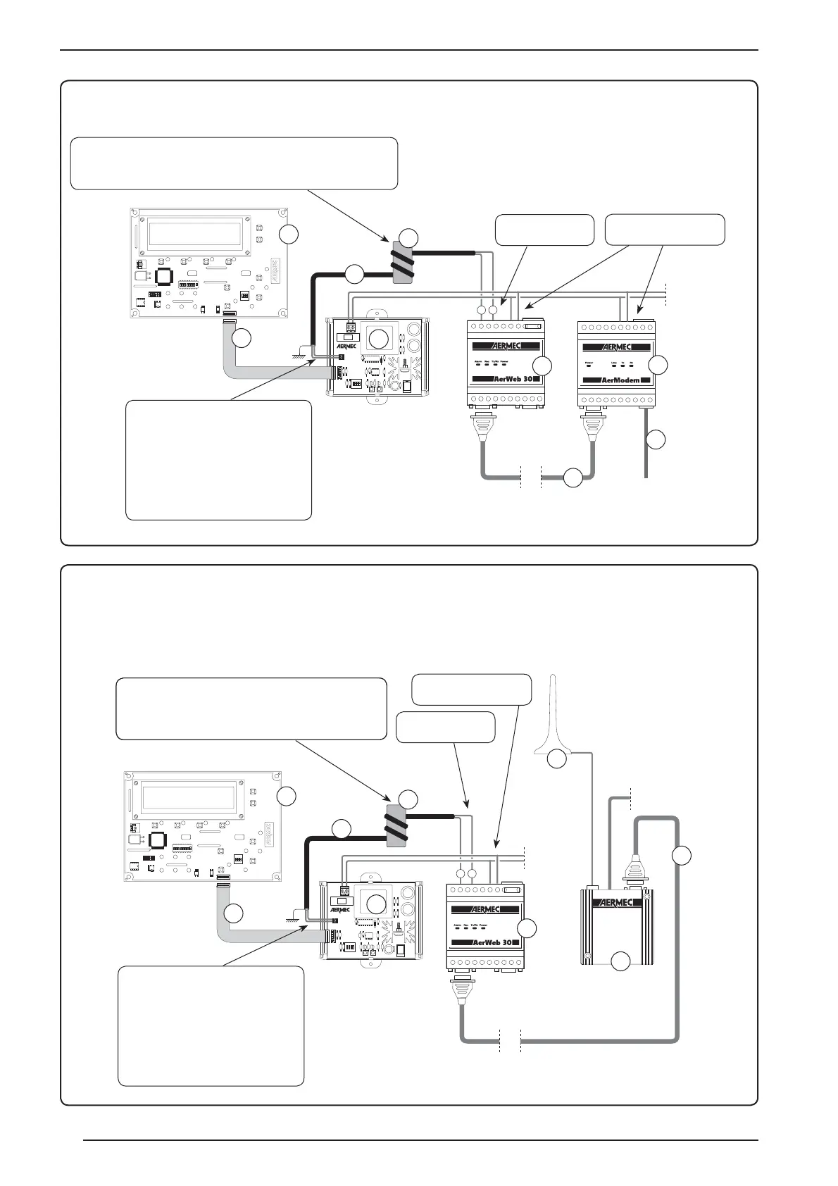
AER485 connection with GR03, AerWeb30 and AerModem
Key
1 - GR03 card
2 - 10-way flexible flat cable
3 AER485 card
4 - AerWeb 30
5 - AerModem
6 - Telephone cable
7 - RS485 serial connection
8 - Serial connection
9 - Ferrite
The serial connection between AER485
and AerWeb 30, must be carried out
using shielded two-pole cable (connecting
the shielding to earth); the name of the
control board for the serial connection is
CONN1; The poles indicated on the card
represent:
Pole A = POSITIVE POLE;
Pole B = NEGATIVE POLE;
The supplied ferrite must be introduced onto the serial connection cable,
positioning it close to the AER485 card. The installation of the ferrite must
be carried out by twisting the cable around the ferrite two times.
Serial connection,
terminals 7 and 8
Power supply connection,
terminals 10 and 12
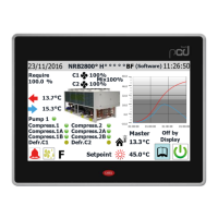
AER485 connection with GR03, AerWeb30 and AerModem GSM
Key
1 - GR03 card
2 - 10-way flexible flat cable
3 AER485 card
4 - AerWeb 30
5 - AerModem GSM
6 - Antenna GSM with cable
7 - RS485 serial connection
8 - Serial connection
9 - Ferrite
230V
~
50Hz
1
2
3
4
5
6
9
8
7
The serial connection between AER485
and AerWeb 30, must be carried out
using shielded two-pole cable (connecting
the shielding to earth); the name of the
control board for the serial connection is
CONN1; The poles indicated on the card
represent:
Pole A = POSITIVE POLE;
Pole B = NEGATIVE POLE;
The supplied ferrite must be introduced onto the serial con-
nection cable, positioning it close to the AER485 card. The
installation of the ferrite must be carried out by twisting the
cable around the ferrite two times.
Serial connection,
terminals 7 and 8
Power supply connection,
terminals 10 and 12
16