7
CARATTERISTICHE
•
FEATURES
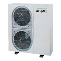
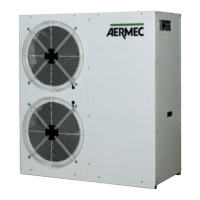
VERSIONI DISPONIBILI
Grandezze disponibili con gas R22:
AN 21 - 3M - 3T - 4 - 6 - 8 - 9 - 11 - 16
Grandezze disponibili con gas R407C:
AN 47 - 67 - 87 - 97 - 117 - 167
Tutte le grandezze possono essere richieste in versione a
pomap di calore. Di seguito vengono elencate le possibili
combinazioni e la relativa descrizione:
H pompa di calore (solo con gas R22)
Descrizione delle sigle delle versioni:
H Pompa di calore: le unità sono predisposte per poter fun-
zionare, oltre che in raffreddamento, anche in riscalda-
mento.
DESCRIZIONE DEI COMPONENTI
1 PANNELLO COMANDI REMOTO
Consente di eseguire a distanza le seguenti operazioni:
– accensione e spegnimento dell’unità ON / OFF (visualiz-
zazione tramite spia gialla);
– selezione del tipo di funzionamento raffreddamento /
riscaldamento (visualizzazione tramite spia verde / rossa);
– riassunto allarmi mediante accensione di una spia rossa.
Nel caso di segnalazione di avvenuto allarme, è possibile
eseguire un’azione di “reset”, dal pannello remoto, agendo
sull’interruttore ON / OFF.
Il collegamento fra l’unità ed il pannello viene eseguito
mediante cavo a 6 poli di sezione: 0,5 mm
2
(max. 50 m), 1
mm
2
(max. 100 m).
2 SCAMBIATORE LATO ARIA
Realizzata con tubi di rame ed alette in alluminio bloccate
mediante espansione meccanica dei tubi.
È del tipo ad elevata efficienza (tubo rigato ed aletta inta-
gliata).
Le grandezze 11, 117, 16 e 167 sono fornite di serie di gri-
glie di protezione delle batterie.
3 GRUPPO VENTILANTE
Costituito da uno o due ventilatori elicoidali azionati diret-
tamente da motori elettrici asincroni monofase con prote-
zione termica interna.
È provvisto di griglia di protezione secondo norme CEI EN
60335-2-40.
4 SCAMBIATORE LATO ACQUA
Del tipo a piastre, è isolato esternamente con materiale a
celle chiuse per ridurre le dispersioni termiche.
5 SEPARATORE DI LIQUIDO (POMPA DI CALORE)
Posto in aspirazione al compressore a protezione da even-
tuali ritorni di liquido.
Non presente sulla versione AN-H 9.
6 QUADRO ELETTRICO
Contiene la sezione di potenza e la gestione dei controlli e
delle sicurezze.
La tastiera di comando consente il controllo completo
dell’apparecchio. Per una più dettagliata descrizione si fac-
cia riferimento al manuale d’uso.
7 VALVOLA INVERSIONE CICLO (POMPA DI CALORE)
Inverte il flusso di refrigerante al variare del funzionamento
estivo / invernale.
8 PRESSOSTATO DIFFERENZIALE
Fornito di serie su tutte le grandezze, è montato tra entrata e
uscita dello scambiatore e, in caso di portata d’acqua trop-
po bassa, ferma il compressore (sia in riscaldamento che in
raffreddamento).
9 COMPRESSORE
Di tipo ermetico ad elevata efficienza (rotativo per i modelli
AN 21 e AN-H 21, scroll per i modelli AN 9 e AN-H 9),
VERSIONS AVAILABLE
Sizes available with gas (R22):
AN 21 - 3M - 3T - 4 - 6 - 8 - 9 - 11 - 16
Sizes available with gas (R407C):
AN 47 - 67 - 87 - 97 - 117 - 167
The above sizes are available in heat pump version. The fol-
lowing is a list of possible combinations with relative
description:
H heat pump (only with gas R22)
Description of version codes:
H Heat pump: unit pre-arranged also for hot water produc-
tion.
COMPONENT DESCRIPTION
1 REMOTE CONTROL PANEL
For remote control of the following operations:
– unit ON / OFF (yellow lamp display);
– operation mode selection cooling / heating (green / red
lamp display);
– summation of alarms by illumination of red lamp.
An alarm can be reset from the remote control panel by
pushing the ON / OFF switch.
The connection between the unit and the panel is made by
means of a 6 pole cable with a section of: 0,5 mm
2
(max.
50 m), 1 mm
2
(max. 100 m).
2 AIR SIDE HEAT EXCHANGER
With copper tubes and aluminum fins locked by mechani-
cal expansion of the tubes, high efficiency type (inner groo-
ved tube and slit fins).
Models 11, 117, 16 and 167 are standard supplied with
heat exchanger protection grills.
3 FAN SECTION
It is made of an helicoidal fan directly coupled to an asyn-
chronous, singlephase electric motor with inner thermal
protection. The fan section is provided with a protection
grill according to CEI standard EN 60335-2-40.
4 WATER SIDE HEAT EXCHANGER
Plate type, externally insulated with closed cell material to
reduce heat losses.
5 LIQUID SEPARATOR (HEAT PUMP)
Position to the compressor inlet to protect against liquid
return.
Not present on the AN-H 9 version.
6 SWITCHBOARD
It contains the power section and the management of the
controls and safeties.
The control keyboard allows a total control of the unit. For a
detailed description, see the instruction manual.
7 4 WAY VALVE (HEAT PUMP)
Inverts the flow of refrigerant when the summer / winter
operation mode is changed.
8 DIFFERENTIAL PRESSURE SWITCH
Standard supplied in all model, it is installed between the
water exchanger inlet and outlet and cuts off the compres-
sor (both on heating and cooling modes) in case of poor
water flow rate.
9 COMPRESSOR
Hermetic (rotary on mod. AN 21 and AN-H 21, scroll on
mod. AN 9 and AN-H 9), high efficiency type, mounted on