28
CARATTERISTICHE
•
FEATURES
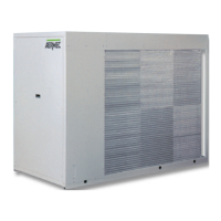
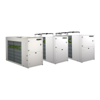
Mod. NRA-C 201 - 202 251 - 252 301 - 302 352 402 502
2027 2527 3027 3527 4027 5027
Ø A mm
2
10 16 16 25 25 35
Ø PE mm
2
10 16 16 16 16 16
F * A 50 63 80 80 100 125
IL A 63 63 80 100 125 125
* = Fusibili di tipo ritardato •
Delayed fuses
.
Gli schemi elettrici sono soggetti ad aggiornamento; è opportuno fare riferimento allo schema elettrico allegato all' apparecchio.
Wiring diagrams may change for updating. It is therefore necessary to refer always to the wiring diagram inside the units.
AA = Relé ausiliario di avviamento
Starting auxliary relay
AP = Pressostato di alta pressione
High pressure switch
APA = Relé ausiliario PA
PA auxliary relay
AT = Relé ausiliario temporizzatore 6’
6’ timer auxliary relay
BP = Pressostato di bassa pressione
Low pressure switch
CC = Contattore compressore
Compressor contactor
COM = Commutatore
Selector switch
CP = Compressore
Compressor
CVC = Contattore ventilatore
Fan contactor
F = Fusibili di linea
Line fuses
IAD = Interruttore orario
Timer
IL = Interruttore di linea
Line main switch
IMA = Interruttore magnetotermico
Magneto-thermal switch
LB = Lampada di blocco
Lock warning light
LF = Lampada di funzionamento CP
CP operation light
MP = Modulo di protezione CP
CP protection module
MQC = Morsettiera quadro comando
Control board terminal board
MTCC = Magnetotermico protezione compressore
Compressor magneto-thermal protection
MTVC = Magnetotermico di protezione MV
MV magneto-thermal protection
MV = Motore ventilatore
Fan motor
NA = Contatto normalmente aperto
Contact normally open
NC = Contatto normalmente chiuso
Contact normally closed
PA = Pulsante di avviamento e sblocco
Start and reset push button
R = Resistenza olio compressore
Compressor oil heater
RCS = Relé controllo sequenza fasi
Phase sequence control relay
TEA = Temporizzatore ritardo avviamento compressore
Compressor delay start timer
TEB = Temporizzatore by pass 3’
3’ by pass timer
TEC = Temporizzatore avviamento compressore 6’
6’ delay compressor start timer
TER = Temporizzatore reinserzione automatica 5”
5” automatic resetting timer
TRF = Termostato regolazione freddo
Cooling thermostat
VSL = Valvola solenoide intercettazione liquido
Liquid gate solenoid valve
Collegamenti da eseguire in loco
On-site wiring
Componenti non forniti
Components not supplied
BL =
Blu
- Blue
MA =
Marrone
- Brown
NE =
Nero
- Black
LEGENDA PER SCHEMI ELETTRICI •
WIRING DIAGRAMS KEY
DATI ELETTRICI •
ELECTRICAL DATA