Do you have a question about the AERMEC NRP 0800 and is the answer not in the manual?
Describes the different system configurations available for the units.
Outlines crucial safety guidelines for installation, operation, and maintenance.
Displays the graphical representation of the unit's cooling operational limits.
Instructions for inspecting the unit upon receipt to ensure it is undamaged and complete.
Advises on selecting an appropriate outdoor location, avoiding specific environmental factors.
Specifies the required clearance distances for installing a single unit.
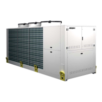
Presents dimensional drawings and data for the NRP 0800-1000 series units.
Details the required water quality parameters for optimal heat exchanger performance.
Provides essential recommendations for connecting hydraulic circuits and components.
Explains procedures for draining the system to prevent freezing damage.
Outlines methods and precautions for protecting the hydraulic system from freezing.
Shows hydraulic connection points for NRP 0800-0900 units with the "00" version.
Illustrates hydraulic connections for NRP 0800-0900 models with specific pump/recovery configurations.
Displays hydraulic connection layouts for NRP 1000 units in the "00" version.
Shows hydraulic connection diagrams for NRP 1000 models with various pump/recovery setups.
Hydraulic connection details for NRP 1250-1800 units in the "00" version.
Hydraulic connection diagrams for NRP 1250-1800 units with R1-R2-R3-R4 and P1-P3 configurations.
Illustrates hydraulic connections for NRP 1250-1800 units with R1-R2-R3-R4 and P2-P4 setups.
Defines the minimum water volume required for stable unit operation and reduced start-ups.
Provides guidance on system water capacity based on expansion vessel size.
Explains how to calibrate the expansion tank pressure based on installation height.
Illustrates the hydraulic circuit diagram for the 2-pipe system configuration.
Details the hydraulic circuit for 2-pipe systems with specific pump configurations.
Details the hydraulic circuit for 2-pipe systems with alternative pump configurations.
Shows the hydraulic circuit layout for 4-pipe systems without an integrated hydronic kit.
Details the hydraulic circuit for 4-pipe systems with specific pump configurations.
Details the hydraulic circuit for 4-pipe systems with alternative pump configurations.
Illustrates the refrigerant flow for 2-pipe systems producing cold water.
Shows the refrigerant flow for 2-pipe systems producing hot water.
Illustrates refrigerant circuits for producing only hot water for DHW.
Shows refrigerant circuits for simultaneous cold and hot water production.
Depicts refrigerant circuits for hot water production to system and DHW.
Displays the refrigerant flow diagram for 4-pipe systems in cooling mode.
Illustrates the refrigerant circuit for hot water production in 4-pipe systems.
Shows refrigerant flow for simultaneous hot and cold water production in 4-pipe systems.
Instructions for connecting the unit to the main power supply.
Provides electrical specifications and data for the unit's operation.
Table showing peak current values for 230V supply across different configurations.
Table showing peak current values for 575V supply across different configurations.
Table showing peak current values for 208V supply across different configurations.
Critical warnings and procedures for initial unit start-up.
Checks required before applying power: safety, fixing, cables, connections, leaks.
Procedures for applying power: voltage checks, phase balance, compressor sump heater.
Checks for hydraulic connections, pump operation, and water flow.
Final steps before unit activation, including electrical panel closure.
Guidelines for checks and adjustments while the unit is running.
Essential precautions and safety measures to follow during maintenance activities.
Highlights risks related to mechanical components during maintenance.
Describes procedures for routine and extraordinary maintenance tasks.
Lists general maintenance tasks and their recommended frequencies.