1121.05 - 6068956_00
NXP 0500 - 1650 2-PIPE SYSTEM / 4-PIPE SYSTEM
EN
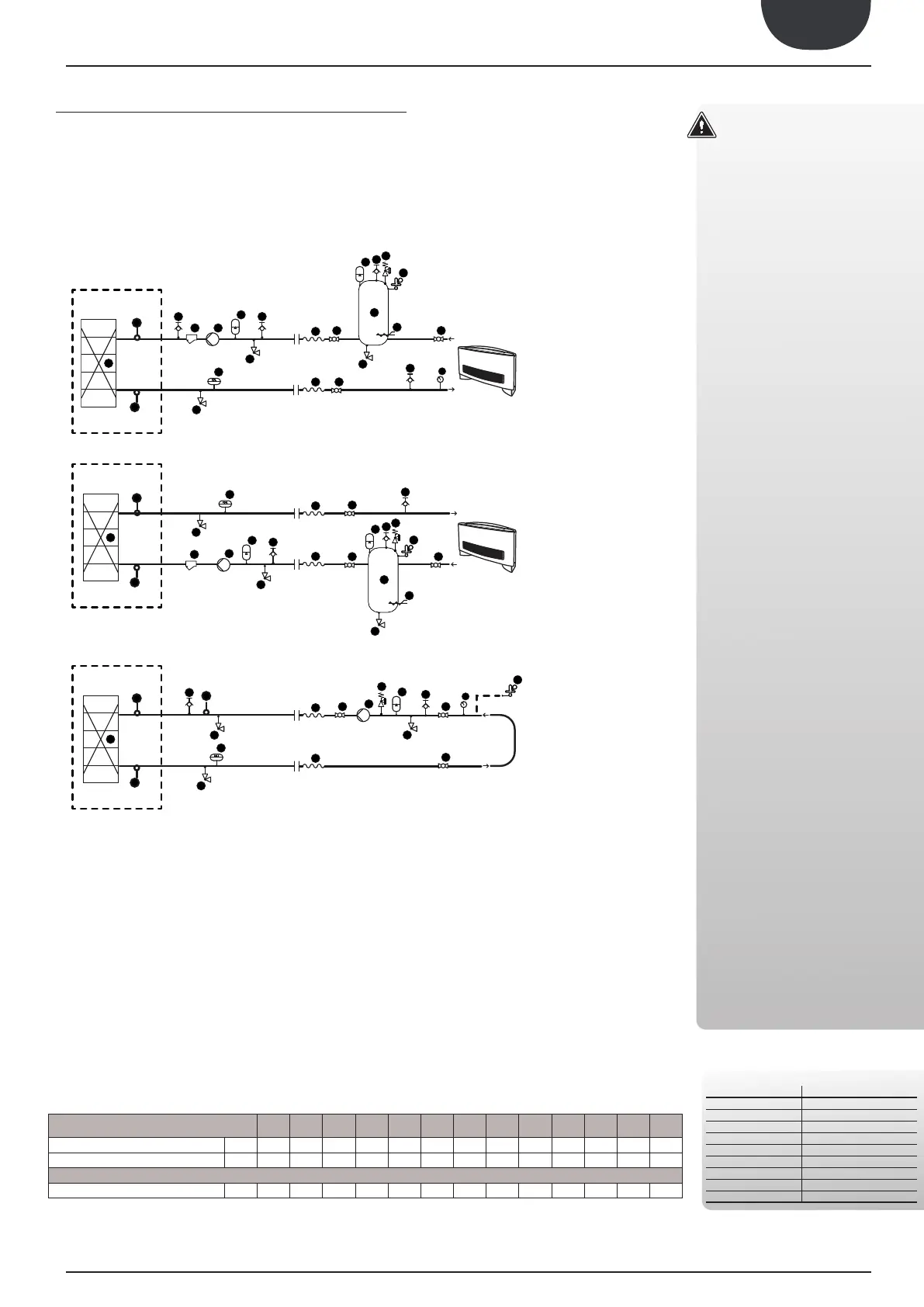
MAIN HYDRAUL IC CIRCUITS
INTERNAL HYDRAULIC CIRCUIT
Model:
HYDRAULIC COMPONENTS
RECOMMENDED OUTSIDE THE UNIT
ATTENTION
..........................................................
1. The choice and installation of compo-
nents outside the units is the installer's
responsibility, who must operate ac-
cording to the code of practice and in
compliance with the Standard in force
in the country of destination.
2. The hydraulic connection pipes to the
machine must be suitably dimen-
sioned for the effective water flow rate
requested by the system when run-
ning. The water flow rate to the heat
exchanger must always be constant.
3. Wash the system thoroughly before
connecting the unit. This cleaning
operation will eliminate any residues
such as welding drips, scale, rust, or
other impurities from the piping. These
substances can also deposit inside and
cause machine malfunctioning. The
connection piping must be adequate-
ly supported so that its weight is not
borne by the appliance.
4.
An appropriate load/reintegration
system must be prepared (if not in-
stalled), which is engaged on the re-
turn line, along with a drain cock in
the lowest part of the system. Water
disconnectors must be used in systems
loaded with anti-freeze or where par-
supply/reintegration waters must be
conditioned with appropriate treat-
ment systems. The "water features"
provided in the table can be used as a
reference.
5. It is prohibited to release water-glycol
mixtures into the environment.
It is recommended to design systems
in order to limit:
• The hourly number of inversions be-
tween operating modes.
• Drop in water temperature during win-
ter defrost cycles.
WATER FEATURES
PH 6-8
Electric conductivity
Chloride ions Less than 50 ppm
Sulphuric acid ions Less than 50 ppm
Total iron Less than 0.3 ppm
Alkalinity M Less than 50 ppm
Total hardness Less than 50 ppm
Sulphur ions none
Ammonia ions
Silicone ions Less than 30 ppm
RECOMMENDED MINIMUM WATER CONTENT
NXP WITHOUT PUMPS
4. MAIN HYDRAULIC CIRCUIT
5
1
13
9
EV
10
15
5
5
5
5
5
1
REC
10
15
5
1
9
CN
13
15
COMPONENTS SUPPLIED AS PER STANDARD
1
- Plate exchanger
5 - Water temperature probes (IN/OUT)
RECOMMENDED COMPONENTS NOT
SUPPLIED FOR WHICH INSTALLER IS RESPONSIBLE
2 - Water filter
3 - Fow switch
4 - Air vent valve
6 - An-vibraon joints
7 - Cut-off valve
8 - Safety valve
9 - Expansion Tank
Exchanger side (hot/cold)
Exchanger side (DHW)
Exchanger side (geothermal)
10 - System buffer tank (installaon recommended
whenever the system water content is less than
that indicated in tab.)
11 - Anfreeze electric heater
12 - Pump
13 - Drain valve
14 - Gauge
15 - Automac fill point
NXP
0500
NXP
0550
NXP
0600
NXP
0650
NXP
0700
NXP
0750
NXP
0800
NXP
0900
NXP
1000
NXP
1250
NXP
1400
NXP
1500
NXP
1650
3/2 3/2 4/2 4/2 4/2 4/2 4/2 4/2 4/2 4/2 4/2 4/2 4/2
l/kW
7 7 7 7 7 7 7 7 7 7 7 7 7
l/kW
14 14 14 14 14 14 14 14 14 14 14 14 14
MINIMUM WATER CONTENT
Compressors / Circuits
System side | Recovery side
RECOMENDED WATER CONTENT
System side | Recovery side
Control on leaving water temperature.
 Loading...