Do you have a question about the AERMEC VED 441 and is the answer not in the manual?
Covers wetness, stepping, stacking, securing, and fragile handling.
Do not handle alone if weight exceeds 25 Kg.
Symbols indicating danger from electricity and moving parts.
General warning symbol for potential hazards.
Covers general warnings, power, usage, cable, and child safety.
Covers room environment, temperature, air jet, cleaning, and filter.
Explains normal operational sounds and basic malfunction steps.
Describes packaging material and refers to control panel manual for use.
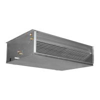
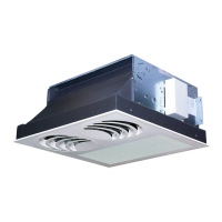
Explains the unit's function and integration into the VMF system.
Lists VED fan coils available in 8 sizes for 2-pipe and 4-pipe systems.
Details features like installation types, VMF system compatibility, and fan specifications.
Shows diagrams for 2-pipe and 4-pipe systems with and without water sensors.
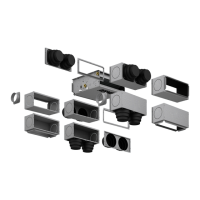
Diagram illustrating the main components of the VED unit with numbered parts.
Covers system types, ventilation, coils, filter, fan, structure, and connections.
Covers suitability, settings, cooling/heating capacity, pressure drops, and sound data.
Covers control panels, accessory compatibility, and ducted model scaling procedures.
Presents operational limits for VED models regarding temperatures, pressure, and power.
Explains water temperature considerations for preventing squeaking and condensate.
Provides heating output and pressure drop data for 2-pipe systems.
Provides cooling capacity, sensible capacity, water flow, and pressure drop for 2-pipe systems.
Includes air flow, static head, motor, input power, sound levels, and coil details.
Provides heating output and water flow rate data for 4-pipe systems.
Provides cooling capacity, sensible capacity, water flow, and pressure drop for 4-pipe systems.
Includes air flow, static head, motor, input power, sound levels, and coil details.
Detailed table showing cooling capacity (Pc) and sensible capacity (Ps) for VED430 across various conditions.
Provides factors to adjust cooling capacity based on fan speed (air flow).
Detailed table showing cooling capacity (Pc) and sensible capacity (Ps) for VED440/441.
Provides factors to adjust cooling capacity based on fan speed (air flow).
Detailed table showing cooling capacity (Pc) and sensible capacity (Ps) for VED530 across various conditions.
Provides factors to adjust cooling capacity based on fan speed (air flow).
Detailed table showing cooling capacity (Pc) and sensible capacity (Ps) for VED540/541.
Provides factors to adjust cooling capacity based on fan speed (air flow).
Detailed table showing cooling capacity (Pc) and sensible capacity (Ps) for VED630.
Provides factors to adjust cooling capacity based on fan speed (air flow).
Detailed table showing cooling capacity (Pc) and sensible capacity (Ps) for VED640/641.
Provides factors to adjust cooling capacity based on fan speed (air flow).
Detailed table showing cooling capacity (Pc) and sensible capacity (Ps) for VED730.
Provides factors to adjust cooling capacity based on fan speed (air flow).
Detailed table showing cooling capacity (Pc) and sensible capacity (Ps) for VED740/741.
Provides factors to adjust cooling capacity based on fan speed (air flow).
Graphs showing heating capacity for different water inlet temperatures and models.
Provides factors to adjust heating capacity based on fan speed.
Graphs showing heating capacity for different water inlet temperatures and models.
Provides factors to adjust heating capacity based on fan speed.
Graphs showing heating capacity for different water inlet temperatures and models.
Provides factors to adjust heating capacity based on fan speed.
Formula DP = DP rated * (QW rated^1.8) / (QW^1.8) for pressure drop calculation.
Table showing pressure drop across cooling coils for different flow rates and models.
Formula DP = DP rated * (QW rated^1.8) / (QW^1.8) for pressure drop calculation.
Table showing pressure drop across heating coils for different flow rates and models.
Formula DP = DP rated * (QW rated^1.8) / (QW^1.8) for pressure drop calculation.
Table showing pressure drop across heating only coils for different flow rates and models.
Graphs illustrating static pressure performance for VED 430 and VED 440 at different fan speeds.
Graph illustrating static pressure performance for VED 441 at different fan speeds.
Graphs illustrating static pressure performance for VED 530 and VED 540 at different fan speeds.
Graph illustrating static pressure performance for VED 541 at different fan speeds.
Graphs illustrating static pressure performance for VED 630 and VED 640 at different fan speeds.
Graph illustrating static pressure performance for VED 641 at different fan speeds.
Graphs illustrating static pressure performance for VED 730 and VED 740 at different fan speeds.
Graph illustrating static pressure performance for VED 741 at different fan speeds.
Graphs showing correction factors for cooling with 10%, 20%, and 35% glycol water.
Graphs showing correction factors for heating with 10%, 20%, and 35% glycol water.
Tables detailing sound power levels (Tot., Lw2, Lw1) for VED 430-440-441 at various frequencies.
Table showing sound pressure levels (A-weighted) measured in a room for VED 430-440-441.
Tables detailing sound power levels (Tot., Lw2, Lw1) for VED 530-540-541 at various frequencies.
Table showing sound pressure levels (A-weighted) measured in a room for VED 530-540-541.
Tables detailing sound power levels (Tot., Lw2, Lw1) for VED 630-640-641 at various frequencies.
Table showing sound pressure levels (A-weighted) measured in a room for VED 630-640-641.
Tables detailing sound power levels (Tot., Lw2, Lw1) for VED 730-740-741 at various frequencies.
Table showing sound pressure levels (A-weighted) measured in a room for VED 730-740-741.
Lists accessories for intake connections, plenums, and flanges.
Lists three-way and two-way water valves for main and heating-only coils.
Lists control panels, interface cards, probes, and VMF system components.
Table showing compatibility of accessories with VED fan coils and configurations.
Explains combinations of VMF system thermostats and control panels.
Outlines combinations for control panels and thermostats, including mandatory accessories.
Lists VMF-SIT3, SIT3, and SIT5 interface cards as mandatory for operation.
Describes the VMF-SIT3 card for VMF thermostats, its function, and limitations.
Explains the functionality and connection of SIT3 and SIT5 interface cards.
Details the VMF system's features, benefits, and expandability for hydronic systems.
Explains the VMF-EO thermostat, its kit contents, management features, and installation.
Explains the VMF-E1 thermostat, its components, management features, and installation.
Details the VMF-E4 control panel, its features, usage, and compatibility warnings.
Shows diagrams for single unit, TTL network, and zone control configurations.
Details the VMF-E5B/E5N supervision interface for managing hydronic systems.
Details the PXAE control panel, its controls, usage, and warnings.
Describes the SW3 accessory water temperature probe for PXAE panels.
Describes WMT05 (2-pipe), WMT06 (2/4-pipe), and WMT10 (electromechanical) control panels.
Describes the RDA_V accessory.
Describes the RPA_V intake plenum with a rectangular flange for rectangular ducts.
Describes the PA_V intake plenum with a circular flange for circular ducts.
Describes the RPM_V delivery plenum with a rectangular flange for rectangular ducts.
Describes the PM_V delivery plenum with a circular flange for circular ducts.
Describes the KFV circular flange kit for connecting additional circular ducts.
Details three-way (VCF45C, VCF47C) and two-way (VCF25C) valves for the main coil.
Details three-way (VCF45H, VCF47H) and two-way (VCF25H) valves for heating-only coils.
Covers general warnings, PPE, electrical wiring, power disconnection, and documentation.
Details unit mounting, hydraulic, condensate, electrical connections, and functional testing.
Covers condensate system checks, sensor placement, and personnel access warnings.
Details making hydraulic connections, using tools, insulation, and sealing.
Instructions for bleeding the hydraulic system and discharging the unit.
Covers direct connection, phase/neutral, disconnection, protection, and 3-phase installation.
Details cable types, minimum section, routing, terminals, and wiring diagrams.
Explains control panel mounting, VMF integration, valve/sensor connections, and wiring precautions.
Describes how to select motor speeds by changing terminal connections.
Details the condensate tray, recommended connections, sealing, and drainage system setup.
Describes how to perform a functioning and seal test of the condensate drain system.
Details the steps for rotating the coil, including disassembly and reassembly.
Highlights the warning to consult the diagram and the importance of sealing after rotation.
Shows dimensional drawings and water/condensate connection sizes for VED 430-541 models.
Shows dimensional drawings and water/condensate connection sizes for VED 630-741 models.
Explains electrical symbols, component abbreviations, and color codes for wiring diagrams.
Illustrates the basic wiring connections for the VED unit, including motor speed selection.
Detailed diagram showing wiring for VED with VMF-EO, VMF-E4, and VMF-SIT3 accessories.
Detailed diagram showing wiring for VED with VMF-E1, VMF-E4, and VMF-SIT3 accessories.
Diagrams showing master and slave unit connections within a VMF network using VMF-E1 and VMF-E4.
Diagrams showing master and slave unit connections within a VMF system using VMF-E1 and VMF-E4.
Diagrams illustrating RS485 serial connections for VMF-E1 and VMF-E5 supervision.
Diagrams showing RS485 serial connections for VMF-E1/E5 with external power supply.
Diagrams illustrating RS485 serial connections for VMF-E1/E5 supervision with MODU-485A.
Diagrams showing RS485 serial connections for VMF-E1/E5 with MODU-485A.
Diagram illustrating wiring for VED unit with SIT3 interface and control panel.
Diagram illustrating wiring for VED unit with PXAE control panel and SIT3 interface.
Diagrams illustrating wiring for VED unit with PXAE, SIT3, and SIT5 accessories.
Diagram illustrating wiring for VED 4-5 series units with WMT10 control panel.
Diagram illustrating wiring for VED 6-7 series units with WMT10 and SIT3 accessories.
Diagram illustrating wiring for VED 4-5-6-7 series units with WMT05 control panel.
Diagram illustrating wiring for VED 4-5-6-7 series units with WMT06 control panel.
Covers low airflow, heating/cooling problems, fan issues, no power, and temperature problems.
Addresses condensation on the unit cabinet and other potential problems.
Details warranty validity, exclusions, repair policies, and contact information.
States AERMEC's participation in the EUROVENT FCU program and where to find product information.
Notes that technical data is non-binding and provides company contact information.