Do you have a question about the AERMEC VED 641 and is the answer not in the manual?
Instructions for manual storage and reading warnings for safety and proper operation.
Procedure for handling unlisted malfunctions and warranty exclusions.
Notes on technical data binding, product changes, and availability of configurations.
Instructions for handling, stacking, and moving the unit safely.
Identification and explanation of key safety symbols used in the manual.
Critical warnings regarding power supply, improper use, temperature regulation, and air jet.
Guidance on periodic filter cleaning and normal operating sounds.
Steps for diagnosing and resolving unit malfunctions, including safety precautions.
Detailed procedure for removing, cleaning, and reinstalling the air filter.
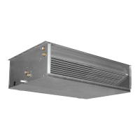
Explains the function of VED fan coils and their integration into the VMF system.
Lists the available sizes for VED fan coils in 2-pipe and 4-pipe systems.
Highlights key features like installation, VMF compatibility, coil types, and fan characteristics.
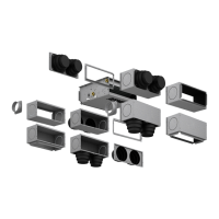
Illustrates system configurations with diagrams and key for water and air connections.
Diagram identifying the main physical components of the VED unit.
Detailed explanations of system types, ventilation, coils, structure, and connections.
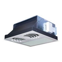
Guidance on installation types, speed settings, and static pressure adjustment.
Information on accessory compatibility and integration with control panels.
Explanation of how technical data, cooling capacities, and pressure drops are presented.
Procedure for scaling ducted models based on duct pressure drops.
Table detailing operational limits (temperatures, pressure, flow rates) for VED models.
Table correlating ambient conditions with minimum average water temperature.
Comprehensive technical data including heating, cooling, air flow, and sound levels.
Comprehensive technical data including heating, cooling, air flow, and sound levels.
Tables detailing cooling capacity based on water and air temperatures.
Tables detailing cooling capacity based on water and air temperatures.
Tables detailing cooling capacity based on water and air temperatures.
Tables detailing cooling capacity based on water and air temperatures.
Tables detailing cooling capacity based on water and air temperatures.
Tables detailing cooling capacity based on water and air temperatures.
Tables detailing cooling capacity based on water and air temperatures.
Tables detailing cooling capacity based on water and air temperatures.
Graphs showing heating capacity vs. water flow rate for different water temperatures.
Graphs showing heating capacity vs. water flow rate for different water temperatures.
Graphs showing heating capacity vs. water flow rate for different water temperatures.
Correction factors for heating capacity at different fan speeds.
Tables showing pressure drop for cooling coils with water at 7°C.
Tables showing pressure drop for heating-only coils with water at 70°C.
Graphs showing useful static pressure vs. air flow rate for different fan speeds.
Graphs showing useful static pressure vs. air flow rate for different fan speeds.
Graphs showing useful static pressure vs. air flow rate for different fan speeds.
Graphs showing useful static pressure vs. air flow rate for different fan speeds.
Graphs showing useful static pressure vs. air flow rate for different fan speeds.
Graphs showing useful static pressure vs. air flow rate for different fan speeds.
Graphs showing useful static pressure vs. air flow rate for different fan speeds.
Graphs showing useful static pressure vs. air flow rate for different fan speeds.
Graphs showing correction factors for cooling mode with varying glycol concentrations.
Graphs showing correction factors for heating mode with varying glycol concentrations.
Sound power levels expressed in dB(A) for VED 430-440-441 models.
Sound pressure levels measured in dB(A) for VED 430-440-441 models.
Sound power levels expressed in dB(A) for VED 530-540-541 models.
Sound pressure levels measured in dB(A) for VED 530-540-541 models.
Sound power levels expressed in dB(A) for VED 630-640-641 models.
Sound pressure levels measured in dB(A) for VED 630-640-641 models.
Sound power levels expressed in dB(A) for VED 730-740-741 models.
Sound pressure levels measured in dB(A) for VED 730-740-741 models.
Introduction to the accessory compatibility table for VED fancoils.
Lists compatible intake/delivery connections, plenums, and flanges.
Lists compatible 3-way and 2-way water valves for main and heating-only coils.
Lists compatible control panels, interface cards, and probes.
Lists compatible VMF system thermostats, control panels, and components.
Notes on accessories and fan coil configurations for single units and networks.
Combinations of VED units with VMF-System thermostats and control panels.
Combinations of VED units with standard control panels and thermostats.
Information on control panel interface cards (SIT3, SIT5) and water temperature probes.
Lists accessories like VMF-SIT3, SIT3, and SIT5 that are mandatory for unit operation.
Detailed description and specifications of the VMF-SIT3 interface card.
Description of SIT3 and SIT5 interface cards and their functionalities.
Explanation of the VMF system's capabilities for hydronic system management.
Details and features of the VMF-EO electronic thermostat for fan coils.
Lists functions manageable with the VMF-EO thermostat, like fan speed and valve control.
Information on the VMF-E1 electronic thermostat kit and its components.
Lists functions manageable with the VMF-E1 thermostat, including fan control and sensors.
Details and usage of the VMF-E4 control panel for VMF series thermostats.
Diagrams showing control panel connections for single units and TTL networks.
Details the VMF-E5B/E5N interface for system management and plant control.
Highlights the plant management capabilities and features of the VMF-E5 panel.
Lists compulsory control panels and thermostats for unit operation.
Details the PXAE multifunction electronic room thermostat.
Information on the SW3 minimum water temperature sensor.
Details of WMT05, WMT06, and WMT10 thermostat control panels.
Description and dimensions of the RDA_V straight intake coupling.
Description of the RPA_V intake plenum with rectangular flange.
Description of the PA_V intake plenum with circular flange.
Description of the RPM_V delivery plenum with rectangular flange.
Description of the PM_V delivery plenum with circular flange.
Description of the KFV circular flange kit for intake or delivery plenums.
Lists compatible motorized 3-way and 2-way valves for the main coil.
Lists compatible motorized 3-way and 2-way valves for the heating-only coil.
Safety warnings regarding power disconnection, PPE, compliance, and qualified personnel.
General indications for proper installation, including duct provisions and unit positioning.
Step-by-step instructions for mounting, connecting, and checking the unit.
Checks for condensate system, fittings, insulation, and functional tests after installation.
Instructions for making hydraulic connections, including safety warnings and bleeding the system.
Guidance on electrical connection requirements, safety, cable types, and panel integration.
Instructions for connecting and testing the condensate discharge system.
Step-by-step guide and diagrams for rotating the coil for hydraulic connections.
Dimensional drawings and connection sizes for specific VED models.
Dimensional drawings and connection sizes for specific VED models.
Key for understanding symbols and abbreviations used in wiring diagrams.
Wiring diagram for the VED unit, motor speed control, and basic connections.
Wiring diagram for VED units with VMF-EO, VMF-E4, and VMF-SIT3 components.
Wiring diagram for VED units with VMF-E1, VMF-E4, and VMF-SIT3 components.
Wiring diagram for VMF-E1 master and slave configurations.
Wiring diagrams for VMF-E5 and VMF-E4 components.
Wiring diagram for VMF-E1 master and slave configurations.
Wiring diagrams for VMF-E5 and VMF-E4 components.
Diagram for RS485 supervision using external VMF-E5 power supply.
Wiring diagrams for VMF-E4, VMF-E1, and VMF-E5 components.
Diagram for RS485 supervision with VMF-E5 external power supply.
Wiring diagrams for VMF-E1 and VMF-E5 components.
Diagram for RS485 supervision with VMF-E5 power supply.
Wiring diagrams for VMF-E1 and VMF-E5 components.
Wiring diagram for the VMF-E01 component.
Wiring diagram for VMF-E1 connected with MODU_485A.
Wiring diagrams for VMF-E2, VMF-E4, and VMF-E5 components.
Wiring diagram for VED unit connected to SIT3 control panel.
Wiring details for the motor speed (MV) connections.
Wiring diagram for VED unit with PXAE, SIT3, and SIT5 accessories.
Wiring details for the motor speed (MV) connections.
Wiring diagram for VED unit with SIT3 and SIT5 accessory combinations.
Wiring details for the motor speed (MV) connections.
Wiring diagram for VED 4-5 units with WMT10 control panel.
Wiring details for the motor speed (MV) connections.
Wiring diagram for VED 6-7 units with WMT10 and SIT3 accessories.
Wiring details for the motor speed (MV) connections.
Wiring diagram for VED 4-5-6-7 units with WMT05 control panel.
Wiring details for the motor speed (MV) connections.
Wiring diagram for VED 4-5-6-7 units with WMT06 control panel.
Wiring details for the motor speed (MV) connections.
Addresses issues like low airflow, lack of heating, or cooling, and their causes.
Troubleshooting for blocked filters and problems with hot/cold water supply.
Addresses problems related to control panel settings, power supply, and water temperature.
Troubleshooting for condensation on the unit's exterior.
Instruction to contact service for unlisted anomalies.
Details warranty validity, conditions, exclusions, and maintenance.
Information on AERMEC's participation in the EUROVENT FCU program.
Statement that technical data is not binding and AERMEC reserves modification rights.