60
IVEDPY 1110 - 4879010_01
The unit must be connected directly to
an electrical outlet or to an indepen-
dent circuit.
WARNING: WARNING: it is com-
pulsory to connect the power cables
Phase (L) and Neutral (N) to the
respective terminals, do not to reverse
the connections, and observe the wir-
ing diagram.
Install a device, main switch, or elec-
tric plug so you can fully disconnect
the device from the power supply.
To protect the unit against short cir-
cuits, fit an omnipolar thermal-mag-
netic trip 2A 250V (IG) to the power
line with a minimum contact opening
distance of 3mm.
For installations with three-phase power
supply, the following precautions
should be considered:
1. In the presence of breakers or ther-
momagnetic switches 3P + N, the trig-
gering current must be at least 170%
of the total load absorbed by the fan
coils for each phase.
2. The section of the neutral wire must
be of a dimension taking into consid-
eration the operating current equal to
170% of the total load absorbed by
the fan coils for each phase.
CHARACTERISTICS OF THE
CONNECTION CABLES
Use H05V-K or N07V-K type cables
with 300/500 V with insulation, routed
through pipes or raceway.
Use a cable with a minimum section of
1mm
2
.
All the cables must be in pipes or race-
ways until they are inside the fan coil.
The cables leaving the pipe or raceway
must be positioned in such a way that
they are pulled or twisted and are any-
way protected from outside agents.
Stranded cables can only be used with
cable terminals. Make sure that the
strands of the wires are inserted properly.
The wiring diagrams are subject to con-
tinuous updates, so it is essential to
use those on the machine as your ref-
erence.
The control panel may not be fitted on a
metal wall unless this is connected to
a grounded outlet permanently.
Before installing the control panel, read
the instructions carefully and config-
ure the panel if necessary. Some con-
trol panels require the combination
with components supplied as acces-
sories, check availability.
WARNING: Make sure the control
panel supports the load of the electric
motor, otherwise placed an SIT3 inter-
face accessory between the fan and
the control panel.
WARNING: The units that are
equipped with VMF series thermostats
must be combined with an VMF-SIT
interface accessory.
When combining to control panels,
the relative wiring diagram must be
respected.
If present, connect the valve and sensor
to the control board, in the positions
indicated in the wiring diagram. In
installations with a 3-way valve, the
minimum water temperature sensor
must be relocated from its standard
mounting in the coil assembly to the
delivery hose upstream of the valve.
If the highest speeds of the motor are
required, change the connection
to the control board on the electric
motor. Follow the wiring diagram.
WARNING:check whether the
installation has been carried out cor-
rectly. FOLLOW THE CHECKING
PROCEDURES indicated in the con-
trol panel manuals.
ELECTRICAL CONNECTIONS
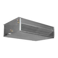
- Make the hydraulic connections.
WARNING: Always use a wrench
and counter-wrench to fix the pipes.
Refer to the size data for the position,
type and diameter of the hydraulic
connections.
You are advised to adequately insulate
water lines and/or fit the auxiliary
condensate drain tray (available as an
accessory), to prevent dripping during
the cooling function.
After installing, check the seal on the
connections.
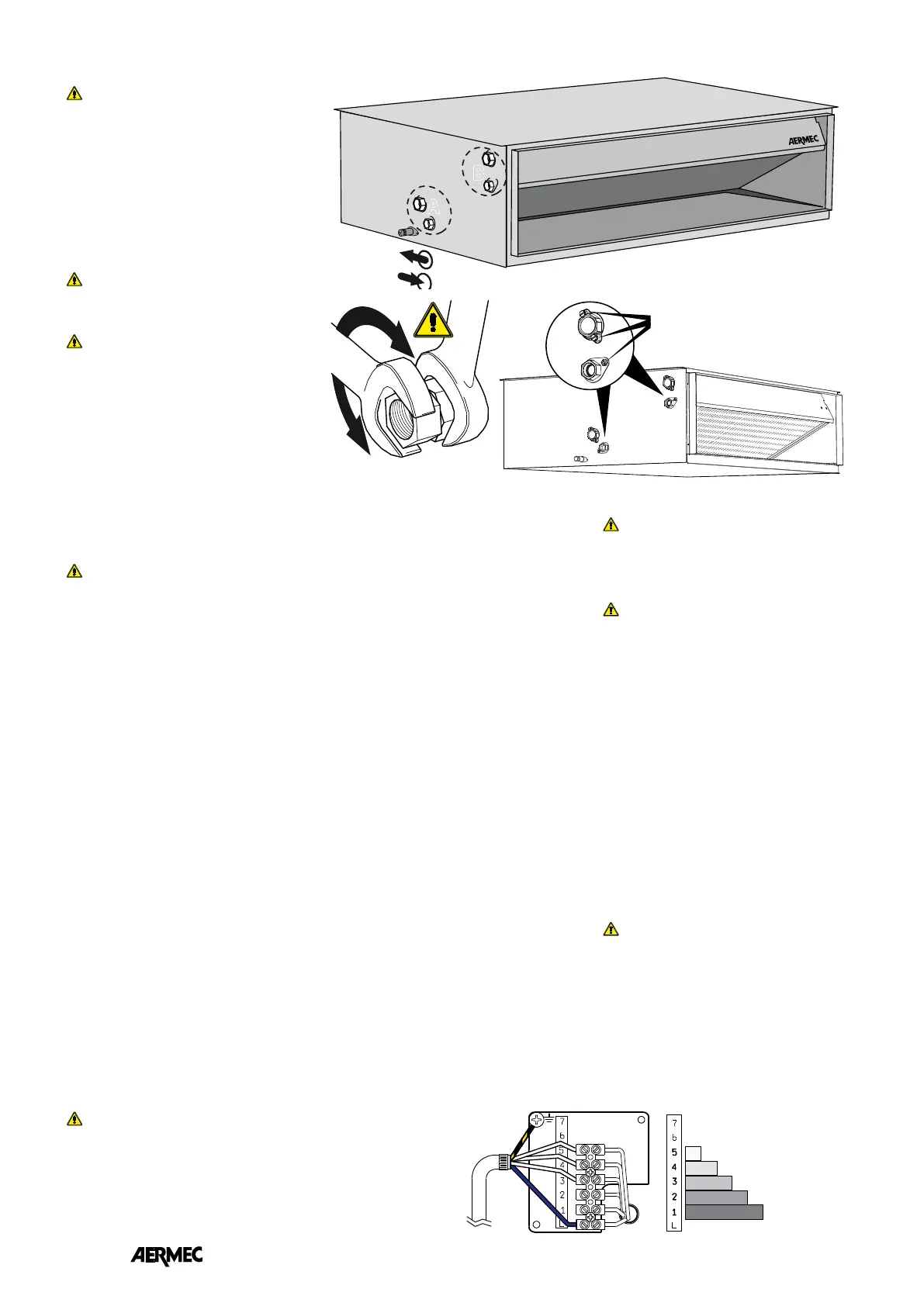
WARNING: Bleed the hydraulic
system. The relief valves are positioned
at the top of the coil near the hydraulic
fittings.
WARNING: To discharge the unit,
use the exhaust valves located in the
lower part of the coil near the hydraulic
fittings.
PLUMBING CONNECTIONS
B
A
IN
OUT
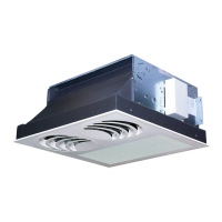
B
Motor control board The 5 speeds of the motor
(5) minimum
(1) maximum
(4 - 3 - 2 )
intermediate
WARNING: VED is supplied with connections to terminals
5 - 4 -3.
To make use of the higher speeds (terminals 2 and 1),
disconnect the wires from the terminals of the default speeds
and connect them to the terminals of the desired speed.
The three speeds must always be adjacent.
Relief valves and discharge
water from the coil