8
IVEDPY 2005 - 4879010_04
SELECTION CRITERIA
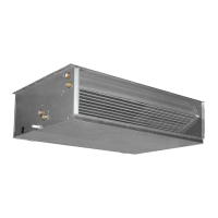
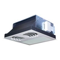
The VED suspended fancoils are suit-
able for both vertical and horizontal
ducted installations.
VED is factory set to operate at the 3
default speeds indicated in the manual.
In case of ducted installations where
pressure drops in the ducts are con-
siderable, the VED allows to achieve
the static pressure necessary to guar-
antee a correct air flow rate by altering
the settings of the electrical box con-
nection on the motor. VED allows the
selection of 3 speed from the 5 avail-
able on the motor.
All versions have to be combined with a
control panel (accessory); consult the
characteristics and compatibility of the
control panels supplied as accessories.
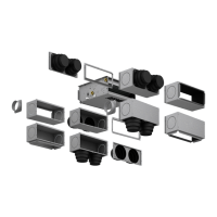
There is a wide range of accessories
for VED fan coils, sometimes some
of them cannot be used at the same
time; check that the accessories are
compatible with the fan coil chosen.
The manual shows the description of
each accessory plus a drawing and its
compatibility.
The installation information is includ-
ed in the manuals supplied together
with each fan coil or its accessory. This
manual is limited to provide general
information in order to obtain a cor-
rect installation; it also contains draw-
ings with fan coil dimensions and the
wiring diagrams with the connections
to control panels.
The main technical data of the VED fan-
coils are summarised in the tables.
The sensible and total cooling capacities
at maximum speed depending on the
incoming water temperature, its ther-
mal head and air temperature with dry
bulb and wet bulb respectively for sen-
sible output and total cooling capacity
are shown in the table and refer to the
high speed; the capacity at the average
and minimum speed are obtained by
multiplying the values obtained from
the table at maximum speed by the
indicated correction factors.
The water pressure drops, respectively
for the 3 - 4 row coils (heating and
cooling) and 1 - 2 row (heating-only)
are illustrated in the diagrams.
The correction factors when the unit
operates with glycol water for cool-
ing and heating function modes are
shown in the graphs in percentages of
glycol of 10%, 20% and 35%.
The heating capacity from the 3 - 4 and
1 - 2 row coils based on the water
flow rate and temperature difference
between the inlet water and inlet air is
shown in a graphical form and refers
to the maximum speed; the perfor-
mances at average and minimum
speeds are obtained by multiplying
the values obtained from the chart at
maximum speed by the corrective fac-
tors indicated.
The pressure level and sound power
of the fancoils at different speeds is
shown in separate tables.
For the ducted installations, the sound
power level is expressed according to
the air flow rate and pressure, and rep-
resented as graphs.
The static pressure for the suspended
versions, according to the air flow rate
and the fan speed, are shown as a
table; the curves are shown for each
reference speed.
For scaling the ducted wall/ceiling-
mounting models, it is advisable to
proceed as follows: choose the size
that in conditions of nominal flow
rate has a power immediately above
that required; afterwards, mark out
the curve of the duct pressure drops
on the rate-pressure diagram related
to the machine in question in order
to individualise the points of machine
operation at the different speeds.
Based on the output values of these
points, you will obtain the correction
factors that help calculate the output
given the actual conditions of air flow
rate.
The above procedure allows to choose
whether to change the settings of the
motor's connections.
 Loading...