4-28 Subject to Export Control, see Cover Page for details.
4-5-2. TRACKING GENERATOR SCREEN FEATURES AND FUNCTIONS (cont)
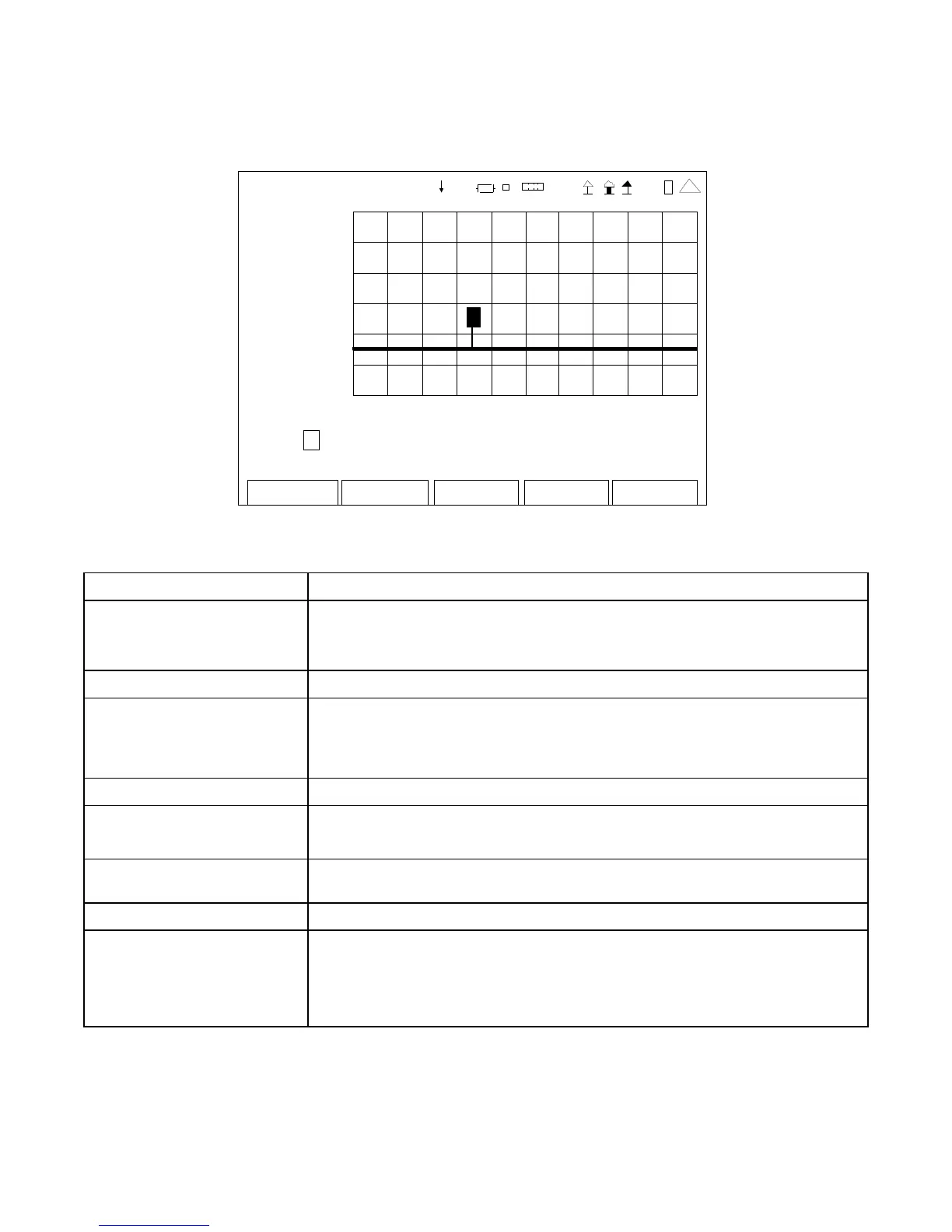
TRACKING GENERATO
10
dB
-8 0
125.0 MHz 175.0
Marker: 1 Off Position: 141.47 Marker 1: -60.2 dBm
Mo ve Lef t Right Marker 2:
Edit Return
Ho l d
RF
41 20 29
1
(Marker Mode)
SCREEN FEATURE FUNCTION
Marker Used to select and enable one of two markers on the Graphical
Display.
Select: 1 or 2
Marker Status Used to set the Marker selected to On or Off.
Position Displays the Horizontal Axis of the Active Marker.
Also used to manually set the location of the Active Marker.
Select: 2.00 to 1000.00 in 0.01 increments
Marker 1 Displays the vertical axis of Marker 1 in dBm.
Move/Min/Max Used to move the Active Marker on the Graphical Display.
Select: Move, Max or Min
Left Right Used with the F1 “Enter” Key to move the Active Marker selected in
the Marker Field to the left or to the right on the Graphical Display.
Marker 2 Displays the vertical axis of Marker 2 dBm.
F1 “Edit” / “Enter” / Done” Edit Highlights the selected field to be changed or changes the
field value if the field only contains two selections.
Enter Moves the Marker the increment selected in the Move field.
Done Ends the Field Edit and saves the new setting / value.
 Loading...


