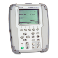
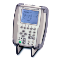
Do you have a question about the Aeroflex ATC-600A-2 and is the answer not in the manual?
Details the manual's structure, chapters, and sections for navigating content.
Overview of the ATC-600A's functions, features, and capabilities.
Procedures for setting up the ATC-600A, including power, battery, and safety.
Identification and description of all front and rear panel controls, connectors, and indicators.
Outlines test procedures for ramp and bench operations and system testing.
Technical details for Transponder, DME, battery, power, fuses, safety, and environmental conditions.
Guidelines for returning test sets for calibration, service, or repair, including packaging.
Recommended precautions for storing the test set for extended periods to maintain integrity.
Lists all input/output connectors, their types, and signal types.
Details the pin assignments for the Altitude Encoder Input Connector.
A chart mapping altitude values to corresponding pulse positions for transmission.
Illustrates the different interrogation modes used in ATCRBS systems.
Explains pulse nomenclature and spacing for Transponder (XPDR) reply codes.
Provides conversion factors for units and nautical distances.
A glossary of abbreviations and acronyms used throughout the operation manual.
| Frequency Resolution | 1 Hz |
|---|---|
| Output Power Accuracy | ±1.0 dB |
| Harmonic Distortion | < -30 dBc |
| Spurious Signals | < -60 dBc |
| VSWR | < 1.5:1 |
| Impedance | 50 Ω |
| Modulation Types | AM, FM, PM, Pulse |
| Interface | RS-232, GPIB |
| Power Requirements | 100-240 VAC, 50/60 Hz |


