Do you have a question about the Aeroflex IFR 4000 and is the answer not in the manual?
Explains safety terms, symbols, and grounding precautions.
Warnings related to the internal battery and potential EMI.
Describes the manual's division into chapters and sections.
Details the IFR 4000 test set's purpose and design.
Lists the features and capabilities of the IFR 4000 test set.
Details the general installation steps for the IFR 4000.
Explains how to operate the IFR 4000 using its internal battery.
Provides instructions for charging the IFR 4000's battery.
Lists essential safety precautions for installation and operation.
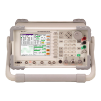
Diagram and labels for the IFR 4000 front panel layout.
General information about performance evaluation.
Step-by-step guide to performing the IFR 4000 self-test.
Overview of operating procedures and available modes.
Explains the fields and parameters for the VOR operational mode.
Explains the fields and parameters for the Localizer operational mode.
Explains the fields and parameters for the Glideslope operational mode.
Details the fields and parameters for the Marker Beacon operational mode.
Explains the fields and parameters for the ILS operational mode.
Details the fields and parameters for the COMM AM operational mode.
Explains the fields and parameters for the COMM FM operational mode.
Details the fields and parameters for the COMM SSB operational mode.
Details the SELCAL mode for testing transceivers with selective calling.
Explains the use of the frequency counter function with the AUX I/O connector.
Procedure for testing short range swept tone emergency beacons.
Details testing procedures for 406 MHz long range position reporting beacons.
Procedure for zeroing the power meter.
Covers CW SWR and Swept SWR measurement procedures.
Step-by-step guide for creating and storing test sequences.
Procedure for deleting stored test sequences.
Instructions on how to recall and execute stored guided test sequences.
Guide to downloading test sequences from the IFR 4000 to a PC.
Guide to uploading test sequences from a PC to the IFR 4000.
Specifications for RF signal generator output levels across different connectors and modes.
Details on harmonics and spurious emissions of the RF signal generator.
Specifies accuracy and modulation parameters for LOC mode.
Specifies accuracy and modulation parameters for G/S mode.
Specifies accuracy and modulation parameters for Marker Beacon mode.
Specifies accuracy and modulation parameters for COMM AM mode.
Specifies deviation range and accuracy for COMM FM mode.
Specifies SELCAL tone accuracy and transmit modes.
Specifies frequency range, resolution, and sensitivity for the counter.
Specifies frequency range, power range, resolution, accuracy, and duty cycle for the power meter.
Details specifications for RF I/O, ANT, SWR, and AUX connectors.
Specifies temperature stability, aging, and accuracy of the time base.
Details the battery type and duration.
Information required for returning test sets for service.
Step-by-step instructions for repacking the test set for shipping.
Lists I/O connectors, their types, signal types, and input/output designations.
Lists applications and their corresponding identification data and protocols.
Instructions for battery and voltage handling for qualified service personnel.
Safety warnings for equipment handling, panel removal, and battery/fuse replacement.
Explains safety terms, symbols, and grounding precautions.
| Modulation Types | AM, FM, PM |
|---|---|
| Input Impedance | 50 ohms |
| Audio Generator Frequency | 20 Hz to 20 kHz |
| Audio Analyzer Frequency | 20 Hz to 20 kHz |
| IBASIC | Yes |
| Tracking Generator | Yes |
| RF Connector Type | N-type |
| Display | Color LCD |
| Power Supply | 100 to 240 VAC, 50/60 Hz |