2-26 Subject to Export Control, see Cover Page for details.
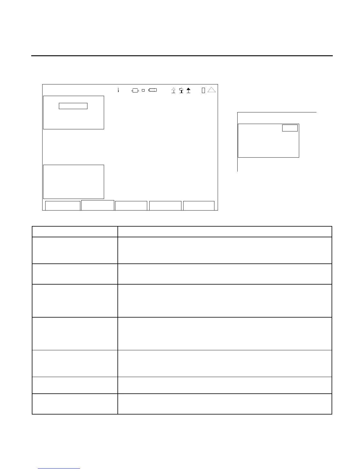
C. Transmitter Test Screen
When the System Menu is displayed, press the 3 Key to access the Transmitter Test Screen:
Edit Re tur
Hold Setup
TRANSMITTER TEST
Receiver More
MH
z: 40.000 00 0
Port: T/ R
Mod: FM 10k
AFBW: No ne
Vo lume: 1 00
Sq uelch: -50 dBm
Sp eake r: Au dio In
Au dOut : Audio In
Sa ve Recal
l
41 20 29
SCREEN FEATURE FUNCTION
MHz Used to select the signal receiver frequency.
Range: 2.000000 to 1000.000000 MHz in 0.000001 MHz
increments
Port Used to select the signal receiver input connector.
Select: Ant or T/R
Mod Used to select the signal receiver modulation type.
Select: AM Modulation Meter changes to AM%.
FM Modulation Meter changes to FM DEV.
IFBW
(field to right of Mod Field)
Used to select the IF bandwidth.
Select: (for AM): 5k, 6.25k, 8.33k, 10k, 12.5k, 25k or 30k
(for FM): 5k, 6.25k, 8.33k, 10k, 12.5k, 25k, 30k, 100k
or 300k
AFBW Used to select the bandwidth filter.
Select: 0.3k LP, 3k LP, 5k LP, 15k LP, CCITT BP, C-Wt BP,
0.3-3k BP, 0.3-5k BP, 0.3-20k BP, 0.3k HP or None.
More Toggles the Receiver Frame to display the Ext Attn dB and Preamp
Fields.
Ext Attn dB Used to select the external attenuation on the input connector.
Select: 0.0 to 30.0 dB in 0.1 dB increments
TRANS MITTER TEST
Receiver More
Ext Attn dB: 0.0
Preamp: Auto