VERIFICATION
IFR 4000
Subject to Export Control, see Cover Page for details. Page 11
Jun 1/11
STEP PROCEDURE
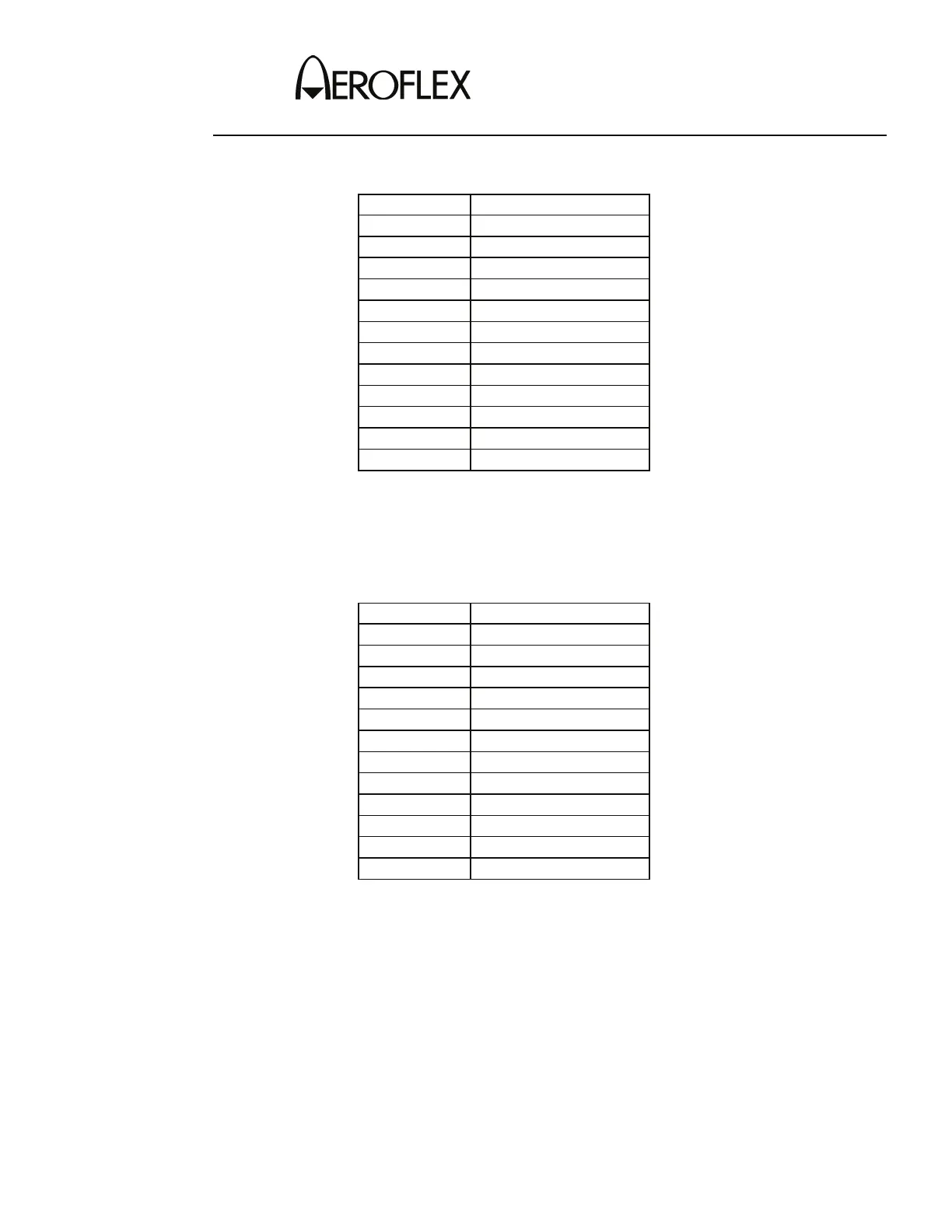
59. Set the RF LVL Field to the following settings and verify levels on the Measuring
Receiver:
RF LVL LEVEL
-12 dBm
-12 dBm (±2.5 dB)
-22 dBm
-22 dBm (±2.5 dB)
-32 dBm
-32 dBm (±2.5 dB)
-42 dBm
-42 dBm (±2 dB)
-52 dBm
-52 dBm (±2 dB)
-62 dBm
-62 dBm (±2 dB)
-72 dBm
-72 dBm (±2 dB)
-82 dBm
-82 dBm (±2 dB)
-92 dBm
-92 dBm (±2 dB)
-102 dBm
-102 dBm (±3 dB)
-112 dBm
-112 dBm (±3 dB)
-120 dBm
-120 dBm (±3 dB)
60. Set the FREQ Field to 334.700 MHz.
61. Calibrate the Measuring Receiver for 334.700 MHz in Tuned RF Level Mode with
a 3.8 Special entered.
62. Set the RF LVL Field to the following settings and verify levels on the Measuring
Receiver:
RF LVL LEVEL
-12 dBm
-12 dBm (±2.5 dB)
-22 dBm
-22 dBm (±2.5 dB)
-32 dBm
-32 dBm (±2.5 dB)
-42 dBm
-42 dBm (±2 dB)
-52 dBm
-52 dBm (±2 dB)
-62 dBm
-62 dBm (±2 dB)
-72 dBm
-72 dBm (±2 dB)
-82 dBm
-82 dBm (±2 dB)
-92 dBm
-92 dBm (±2 dB)
-102 dBm
-102 dBm (±3 dB)
-112 dBm
-112 dBm (±3 dB)
-120 dBm
-120 dBm (±3 dB)
63. Disconnect the Measuring Receiver from the RF I/O Connector.
 Loading...