VERIFICATION
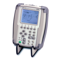
IFR 4000
Subject to Export Control, see Cover Page for details. Page 4
Jun 1/11
(2) RF Accuracy
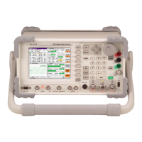
TEST EQUIPMENT: Modulation Analyzer
VERIFICATION FAILURE: If any step in this procedure fails or is out of tolerance,
this indicates a failure in the Test Set. Refer to the
IFR 4000 Maintenance Manual for corrective action.
STEP PROCEDURE
1. Connect the Modulation Analyzer (RF Input) to the ANT Connector.
2. Configure the Modulation Analyzer as an RF Counter.
3. Press the SETUP Key to display the Setup Menu.
4. Set the Test Set as follows:
FIELD SETTING
PORT ANT
GEN FREQ PRESET
5. Press the MODE Select Key until the VOR Mode Screen.
6. Set the Test Set as follows:
FIELD SETTING
FREQ 108.000 MHz
RF LVL -20.0 dBm
MOD TONE OFF
7. Verify 108.0 MHz (±108 Hz) on the Modulation Analyzer.
8. Press the MODE Select Key until the LOCALIZER Mode Screen.
9. Set the Test Set as follows:
FIELD SETTING
FREQ 108.100 MHz
RF LVL -20.0 dBm
MOD TONE OFF
10. Verify 108.1 MHz (±108.1 Hz) on the Modulation Analyzer.
11. Press the MODE Select Key until the GLIDESLOPE Mode Screen.
12. Set the Test Set as follows:
FIELD SETTING
FREQ 334.700 MHz
RF LVL -20.0 dBm
13. Verify 334.7 MHz (±334.7 Hz) on the Modulation Analyzer.
14. Press the MODE Select Key until the MARKER BEACON Mode Screen.
15. Set the Test Set as follows:
FIELD SETTING
FREQ 75.000 MHz
RF LVL -20.0 dBm
MOD TONE OFF
16. Verify 75.0 MHz (±75 Hz) on the Modulation Analyzer.
17. Press the MODE Select Key until the COMM AM Mode Screen is displayed.
 Loading...


