Hardware Reference Guide 99
PRODUCT OVERVIEW
PRODUCT OVERVIEW
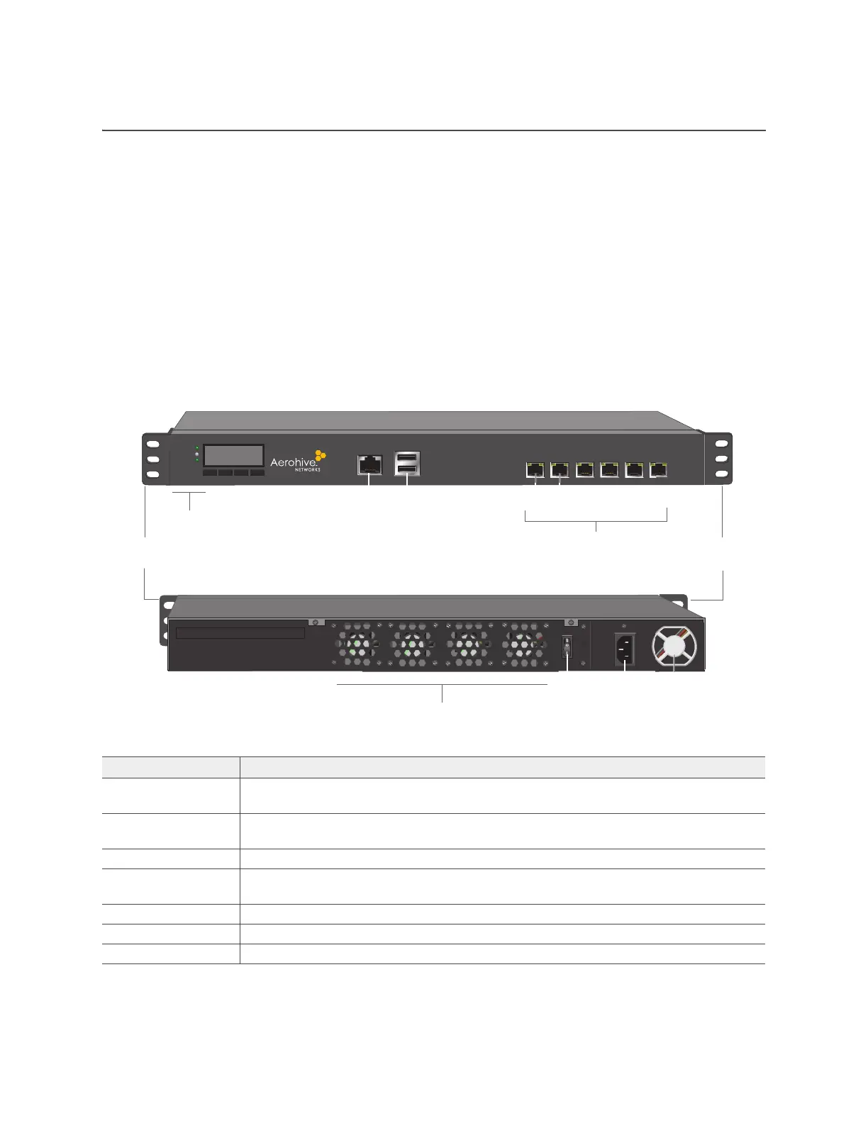
The Aerohive 1U High Capacity HiveManager Appliance is a central management system for configuring
and monitoring devices. You can see the hardware components in Figure 1 and read a description of each
component in Table 5 "HiveManager Appliance component descriptions".
The HiveManager Appliance ships with the following items:
• HiveManager Appliance chassis
• 2 Ethernet cables (one straight-through and one crossover cable)
• One power cord
• One console cable (DB9 to RJ45)
• Two mounting brackets and mounting screws
Figure 1 HiveManager Appliance hardware components
Table 5 HiveManager Appliance component descriptions
Component Description
Mounting brackets Mounting brackets allow you to install the chassis in a front- or mid-mount position in
a standard 19" (48.26 cm) equipment rack.
Console port The RJ45 Console port allows you to make a console connection using an RS-232 (or
"null modem") cable. See "Ethernet and Console Ports" on page 100.
USB ports The USB ports are reserved for internal use.
Status LEDs The status LEDs convey operational states for system power, hard disk drive, and port
connections. See "Status LEDs" on page 100.
LCD module Reserved for future use.
Hard disk drive The HiveManager Appliance has a 500 GB hard disk drive.
System memory The HiveManager Appliance has 8 GB of installed system memory.
Front panel
Mounting
bracket
USB ports
Console port
Ethernet ports
Port 1 = MGT, Port 2 = LAN
Ports 3-6 reserved for future use
Mounting
bracket
Status LEDs
POWER
STATUS
HDD
Rear panel
Power
fan
On/Off
switch
AC power
inlet
System fans
Port 1 Port 2