Fig. 31
161
160
165
166
und
164
163
162
Fig. 30
Complete the wheelhouse with the
handrails 160 - 161.
Apply a strip of adhesive tape over the front
of the PILOT name placard to hold the
letters in position, then remove the letters
from the etched parts sheet.
Apply a little contact cement or canopy glue
to the rear face of all the letters, then stick
the name placard to the side of the
deckhouse as shown. Allow the glue to set
hard before cautiously peeling off the
adhesive tape. Important: do not use
cyano-acrylate!
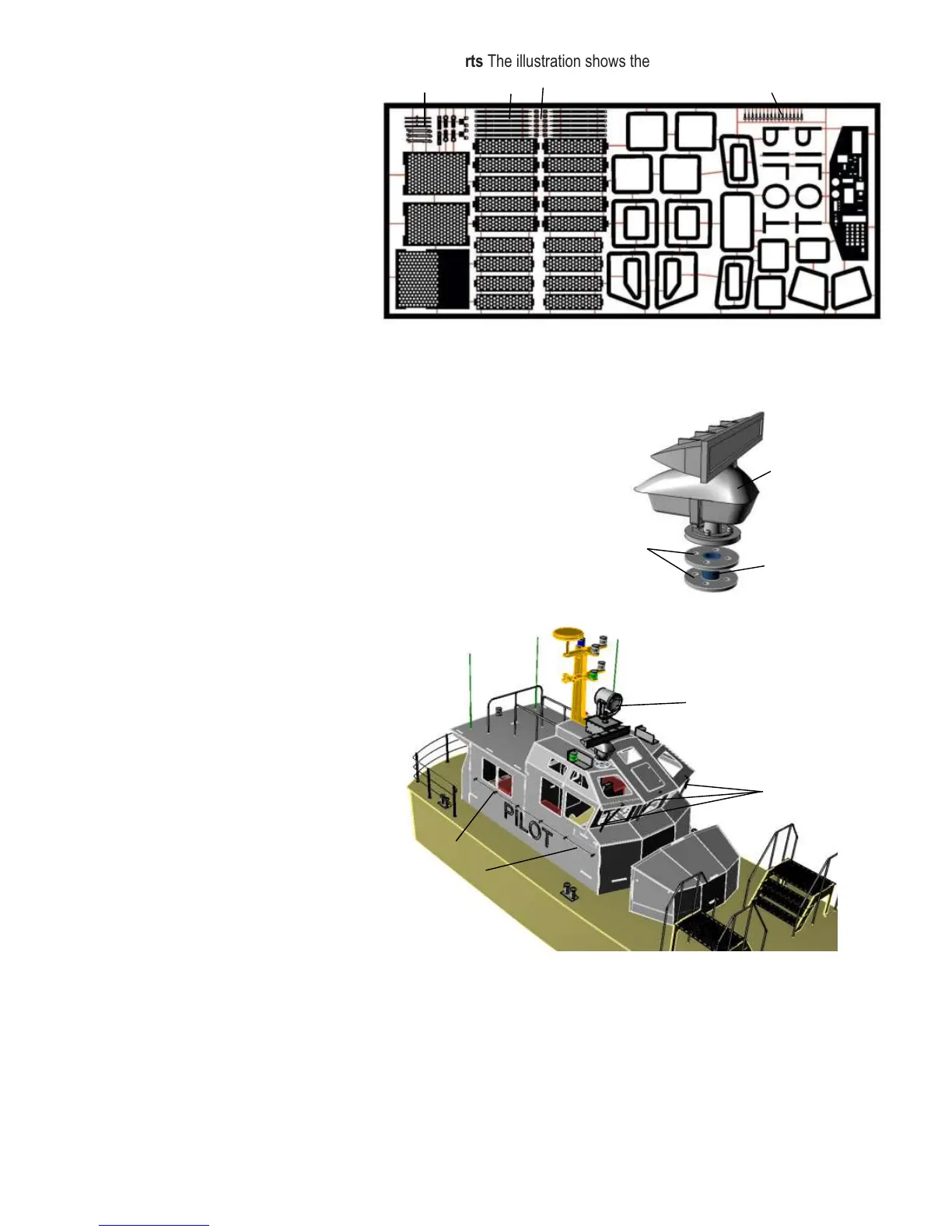
Attach the two radar flanges 162 to the
tube 163, and glue this assembly to the
underside of the radar unit. Paint the radar
unit before gluing it over the hole in the
right-hand side roof panel 101.
Assemble the searchlight 165 as described
in the separate instructions, and glue it over
the hole in the roof.
Assemble the screen wipers 166, and glue
them to the front windows. The wiper
blades can be rotated to the position you
prefer.
Glue the lifebelt to the rear wall of the
wheelhouse or the stern railing.
A rubber band can be connected between
the hook of frame 3 and the hook of the
partition in order to hold the deckhouse in
place.
Etched parts The illustration shows the rear face
156 160 157
166
Each LED should be wired individually to a series resistor (see diagram below), as this ensures long, reliable
operation of the LEDs, as well as simplifying the circuit.
Cut down the LED terminal pins to a length of about 8 mm, leaving the longer pin of each pair slightly longer; these
are the positive (+) terminals. Solder the thin braided wire - or, better, lacquered copper wire - to the pins.
Thread the pairs of wires through the holes in the mast, and test each LED separately before soldering the series
resistors in the circuit downstream of the switches. It is advisable to install a fuse rated at max. 2 A in the battery
circuit.
The circuit shown is only a suggestion.
The lighting system components are not included in the kit.
1. Panoramic light, flashing light, yellow
2. Running light
3. Panoramic light, pilot
4. Panoramic light, mooring light
5. Panoramic light, flasher, blue
6. Searchlight
7. Bow searchlight
8. Battery, 4.8 - 6 V
9. Switch
10. Distributor + and –, 11 series resistors
12. Fuse, max. 2 A
Resistors for coloured LEDs:
6,0V 7,4V
Blue 120 Ohm 220 Ohm
Green 120 Ohm 220 Ohm
Red 220 Ohm 270 Ohm
Withe 120 Ohm 220 Ohm
Yellow 220 Ohm 270 Ohm
Resistors for lamps 7 33 Ohm
The seven switches (10) can be replaced by electronic switching modules. This requires no changes to the model's
wiring arrangement.
We wish you many hours of pleasure building the model, and “working the boat on the water” - by day and by night.
The aero-naut Modellbau team
flat face
Stern
Masthead
Instrument
 Loading...