Fig. 13
51
51
Adhesive tape
Bollard supports
60
62
61
63
Fig. 13.3
Curve the bulwark sections 51 slightly towards the
bow by pulling them over the edge of a table.
Fit both bulwark components in the slots in the deck.
Carefully sand the front edge of both parts 51 where
they meet, so that a watertight glued joint can be
produced.
Slide the lamp support into position, and tape the
bulwark in place. Clamp the bollard supports in
position as shown, as they serve to locate the
bulwark. Apply glue to the joints, then raise the boat
at front and rear in turn to encourage the adhesive to
run behind the tape and into the joint between the
deck and the bulwark. Allow the glue to set hard, then
remove the bollard supports, and run more adhesive
into the inside corner. Remove the adhesive tape and
glue the bollard supports in place. Remove the lamp
support. It is eventually glued between the bulwarks,
but only after the addition of the appropriate etched
parts. The whole hull and deck can now be painted:
the lower hull and bulwark should be black. Peel off
the protective film from the searchlight lenses.
The lamp support can now be painted. Remove the
step treads 61 from the etched parts, and glue them
in the slots of parts 52.
Solder the LEDs to the cable in series, and insert
them in the reflectors (see wiring diagram at the end
of these instructions). Insert the upper tread
assembly 58 / 60, and glue it in place with a non-
permanent adhesive (e.g. Fixogum). The whole lamp
support assembly can now be glued to the deck
between the bulwarks.
Cut the railing components 62 and 63 from 1.5 mm Ø
nickel-silver wire as shown in the bending template in
plate 2. Solder the parts together In the template. Use
at least a 60 W soldering iron to allow the joints to be
completed quickly, without heating up the template
too much. Insert the railing in the holes in the bulwark
and the deck, and glue the assembly in place.
77
74
77
73
75
76
72
71
Fig. 15
78
76
75
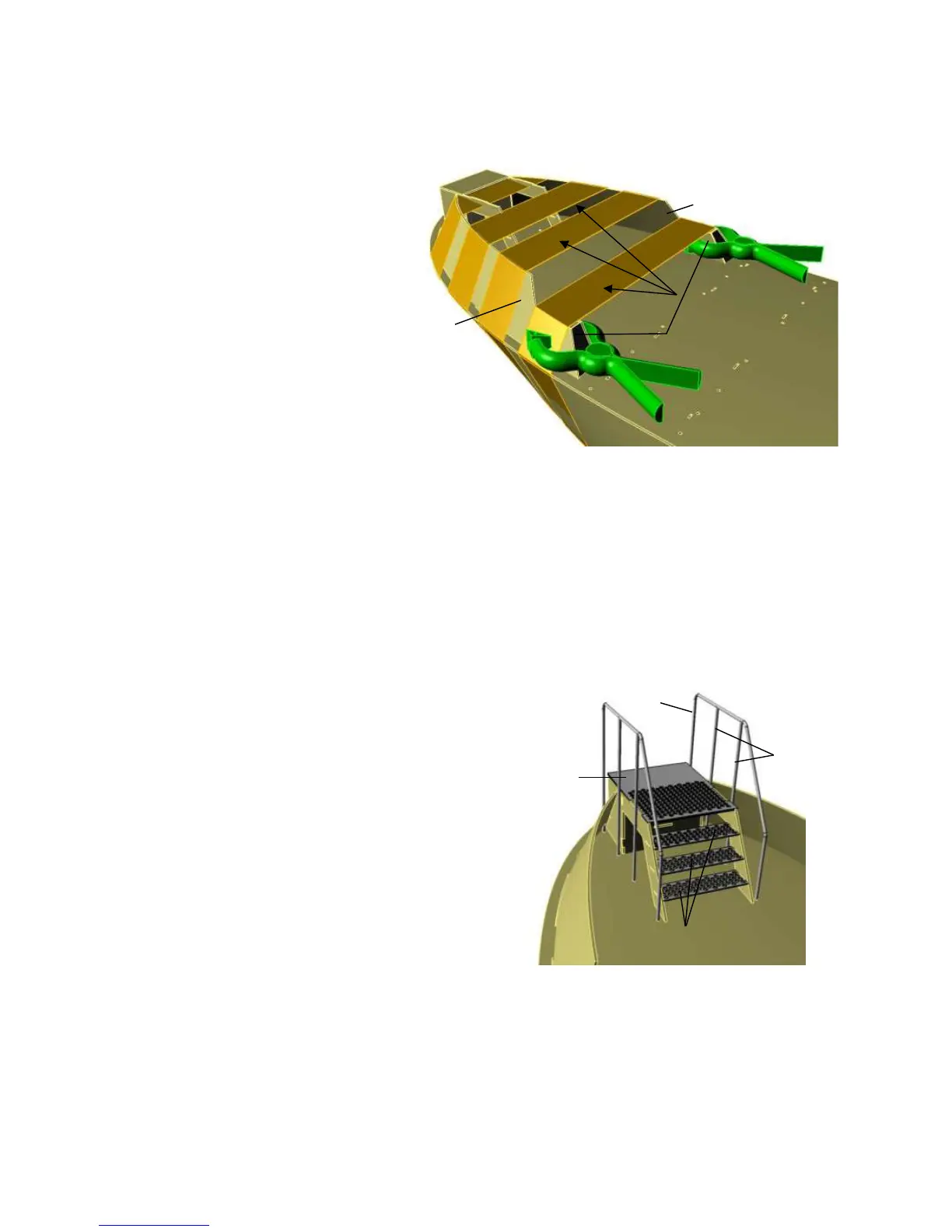
Etched parts The illustration shows the rear face
66
60
61 61
65
Fig. 13.4
68-70
66
67
64
65
62
64.1
Cut the railing components 62 and 67 to length from 1.5 mm Ø
nickel-silver wire, and bend them to the shape shown in the
bending template in sheet 2. Solder the joints with the parts in
the template. Paint the step sides 64 and 64.1, and glue three
treads 65 and one platform 66 between them.
Insert the railings in the slots in the deck and glue them in
place.
Glue the railing in the deck.
Assemble parts 68 - 70 to form the bollards. Paint them black,
and glue them in the bollard supports on the bulwark and deck.
If you wish, you can also fit cross-rails between the bollard
posts as shown.
Glue together parts 71 - 77 to form the weather
shield, fitting them together in the sequence of
the part numbers.
Sand back the angled edges of parts 74 and 77
at the front and side, so that they end flush with
the adjacent panels.
Bend the handrail 78 to shape, and insert it in
the holes in the weather shield
The handrail should be inserted in the slots in
the deck after the model has been painted.
 Loading...