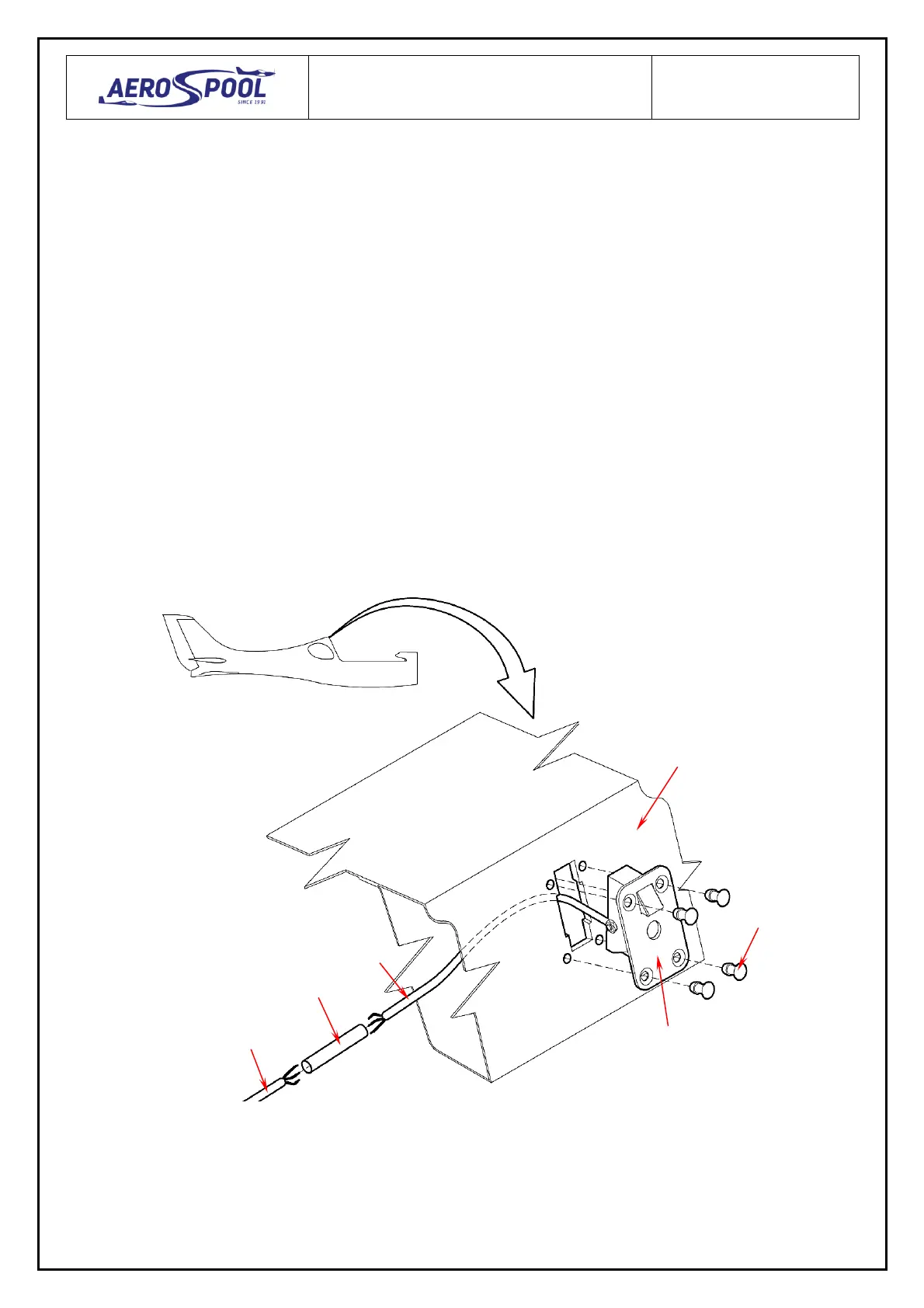
2. Installation of new canopy lock socket.
2.1. Put the insulation (6, Fig. 3) on the cable (5), solder the wires (4, 5) according to wiring diagram
(Fig. 10).
2.2. Place the insulation (6, Fig. 3) on the joint and apply heat to shrink it.
2.3. Pass the cable (7, Fig. 4) to the right through the fuselage stiffener and central tunnel
to the instrument panel.
2.4. From the rear drill the hole in the fuselage stiffener for access to adjusting screw (10, Fig. 5)
of sensor.
2.5. Place the canopy lock socket (1, Fig. 3) into the fuselage (2) and attach it by rivets (3)
(see Fig. 7).
2.6. Fix the cable (7, Fig. 4) to the fuselage and other electrical installation by means of clips (8) and
cable ties (9).
2.7. Connect the cable (7) to the check lamp and circuit breaker according to wiring diagram (Fig. 10).
2.8. Bond the protective plate (11, Fig. 7) on the canopy frame (12) using Araldite 2022-1
in the position according to main latch (13).
Fig. 3