3. Instrument panel and connection
3.1. Variant A (individual check lamp):
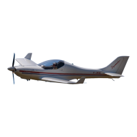
3.1.1. Drill a hole ø8.5 mm for the check lamp (area A, Fig. 8) and ø9.5 mm for the circuit breaker
(area B) on the instrument panel.
3.1.2. Connect the sensor of canopy lock socket to the check lamp and circuit breaker according
to wiring diagram (Fig. 10).
3.1.3. Install the check lamp and circuit breaker on the instrument panel.
3.1.4. Mark the check lamp and circuit breaker by label “CANOPY”.
3.2. Variant B (check lamps panel):
3.2.1. Connect the sensor of canopy lock socket to the pin No. 8 of connector DB37 of check lamps
panel and to the circuit breaker of check lamps panel according to wiring diagram (Fig. 10).
Fig. 8