Do you have a question about the Aerotech A3200 Series and is the answer not in the manual?
Details critical safety procedures, including electrical shock and bodily injury prevention measures.
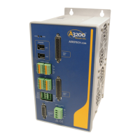
Step-by-step guide for connecting the Nmark GCL, covering device number, FireWire, I/O, and power.
Presents detailed electrical specifications for motor supply, control supply, and output parameters.
Explains how to assign a unique communication channel number using Device Number switches.
Details the wiring and mating connector information for the 85-240 VAC control power supply input.
Details the wiring and mating connector information for the ±40 VDC motor power supply input.
Details the high-speed communications connection using the FireWire bus, including cards, repeaters, and cables.
Describes connections for laser control outputs, available as optically-isolated or 5V TTL signals.
Details PSO specifications and its use for synchronizing outputs with feedback position for laser firing.
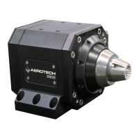
Covers connections for galvo motors, including analog encoder inputs and motor power, with pinout details.
Details the four digital outputs, four digital inputs, one differential analog input, and two analog outputs.
Details the ESTOP input for monitoring external safety circuits and preventing ESTOP fault conditions.
Highlights critical safety warnings regarding disconnecting power and awareness of lethal voltages before maintenance.
| Brand | Aerotech |
|---|---|
| Model | A3200 Series |
| Category | Industrial Equipment |
| Language | English |