2.1 WARNINGS
RISK OF ELECTRIC SHOCK
Failure to follow the instructions in this manual, carries a risk of electric shock.
RISK FOR PEOPLE AND PROPERTY
Failure to follow the prescriptions in this manual, carries a risk of damage to
persons and/or property.
WARNING
Failure to observe the prescriptions in this manual, cause damage to the pump,
the unit or the system.
ATTENTION: PUMPS
• Make sure the pumps are fully primed before you start it.
• Make sure the pumps are running with the correct rotation.
• The electric pumps or the motors can start up automatically.
ATTENTION: ELECTRICAL CONNECTION
• The control panel must be connected by a qualified electrician in compliance
with the electrical regulations in force.
• The electric pumps or the motors and the panel must be connected to an efficient
grounding system in compliance with the electrical regulations locally in force.
• Ground the unit before carrying out any other operation.
ATTENTION: SERVICE
As a general rule, always disconnect the power supply before proceeding to
carry out any operation on the electrical or mechanical components of the unit
or system.
2.2 CAUTION
InstallationSafety informations
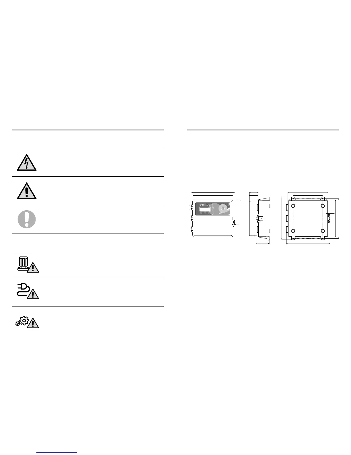
259.9
191.0
273.4
283.0
239.8
257.3
87.2
74.4
Ø 7
fig. 1
3.1 ASSEMBLING
Fix the control panel for a stable support with
screws and screw anchor using the holes
arranged in the box (pic. 1) or the fixing bracket
if present.
To fix the cables in their terminals use a tool
of the proper sizeto avoid the damaging of the
screws or of their seat.
If use an electric screwier pay attention not to
spoil the thread or the screws.
After the fixing, remove every plastic or metallic
surplus (ex. Pieces of copper of the cables or
plastic shavings of the box) inside the box before
suppling power.
Connect the unit at ground before carrying
out any other operation.
The voltage input corresponds to the data
written on the panel and on the pump:
• (400V ± 10% 50/60Hz x il EPIC 1D -400/...)
• (230V ± 10% 50/60Hz x il EPIC 1D -230)
Make sure that the power-supply-cable can bear
the nominal current and connect it to the terminals
of the general switch of the control panel.
If the cables are exposed, they must be
appropriately protected.
The line must be protected with an Earth
leackage and magnetic switch measured in
accordance with the regulations locally in force.
LINE OF SUPPLY CURRENT
Connect the unit at ground before carrying
out any other operation.
The voltage input corresponds to the data
written on the motor:
• (400V±10% 50/60Hz three-phase)
• (230V±10% 50/60Hz single-phase)
Doing some starting make sure that the motor
respects the right direction of rotation usually
indicated by an arrow printed on the motor.
LINE OF MOTOR POWER SUPPLY
 Loading...