9
USA
6.1.2 Connecting the power supply
DANGER
Risk of death by electric shock!
► Connect the product only to a grounded power supply.
Note
The mains voltage must correspond to the voltage indicated on the type
plate at the back of the unit.
► Plug in the power cord at power cord socket 13.
► Connect power supply by inserting into a wall socket.
6.1.3 Switching on the control unit
► Activate the power ON switch 10.
The power ON indicator 9 and indicator light 5 light up.
The control unit 1 always performs a power-on self-test when the unit
is switched on.
If a malfunction is detected, an error message will appear in the
display 2, see system errors.
6.1.4 Switching off the control unit
► Activate the power OFF switch 8.
The power ON indicator 9, the indicator light 5 and the display with
touch control panel 2 will fade out.
6.1.5 Putting out of operation
Note
The safe and all-pole disconnection of the product from the main power
supply is only guaranteed when the power cord is unplugged.
► Switching off the product: Activate the power OFF switch 8.
► Unplug the power cord from the power socket 13.
The operation of the device is safely terminated.
6.1.6 Connecting the ELAN 4 electro to wireless foot control
GA810
The system configuration menu is used to connect the wireless foot con-
trol to the control unit, see Chapter 6.4.4
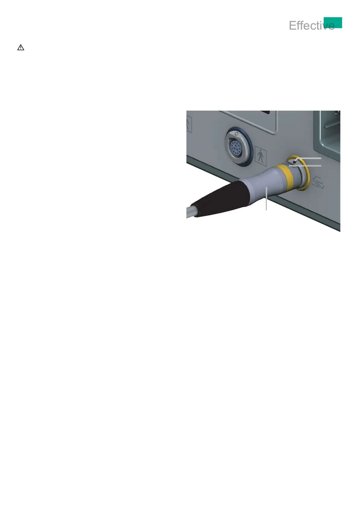
6.1.7 Connecting the ELAN 4 electro foot control GA808 to the
control unit
Note
The plug connection of the foot control has a yellow coded ring and a filled-
in dot.
► Position connector of foot control c so that marking b on the connector
is aligned with marking a on the connection socket for foot control 6,
see Fig.2.
► Plug the connector for foot control c firmly into the connection socket
for foot control 6.
Fig.2 Connecting the foot control
Legend
a Marking for connection socket
b Marking for connector
c Connector for foot control
Document No.: IFU - Version: 3.0 - Document ID: SOP-AIC-5001568 Date/Time Printed/Viewed: 2022-04-13 15:59 (CET)
Effective
 Loading...