4
AMERICAN EXPEDITION VEHICLES
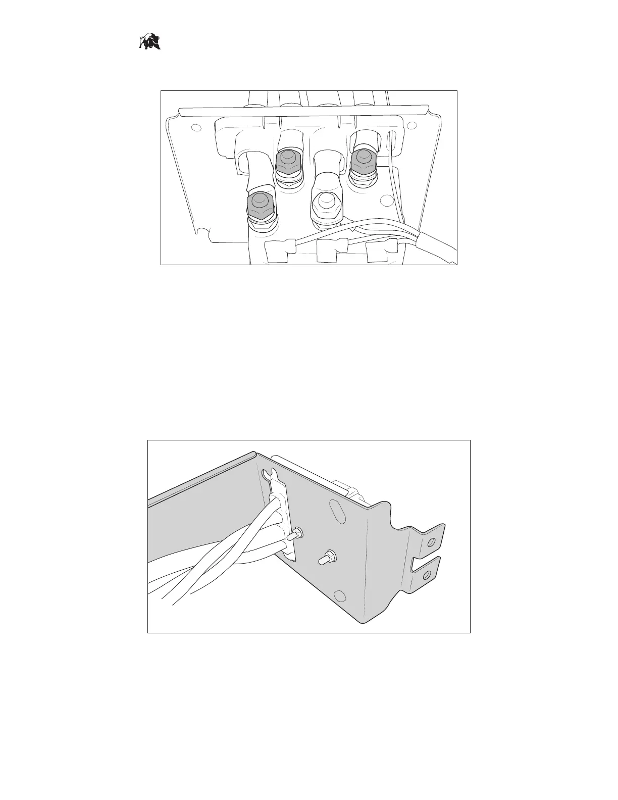
2. Disconnect the leads labeled A, F1, and F2 and remove the Warn harness from the controller (fig. 10).
A
F1
F2
Figure 10
3. Route AEV harness through the AEV bracket and into the controller through the same openings the
Warn harness was removed from.
4. Connect AEV leads. Yellow = A, Green = F1, Blue = F2
5. Isolate the small black motor ground wire inside the controller. Cut and splice in the new motor ground
wire from the AEV harness. NOTE: Make sure the splice will be located within the winch controller
enclosure when reassembled.
6. Mount the controller to the bracket using QTY 2 flange nuts provided. (fig. 11).
7. Reinstall QTY 4 bolts to reassemble controller housing.
Figure 11