-Dati tecnici e caratteristiche soggetti a cambiamenti senza preavviso -Technische Daten und Eigenschaften mit Änderungen ohne Anzeige
-All specifi cation subject to change without notice - Données techniques et caracteristiques suiettes à des changements sans avis
32
2. Connect the pipelines to the unit temperature regulator.
RECOMMENDATIONS
Connection and welding tasks must be performed by qualifi ed personnel having the technical skills required by law in the
Country where the machine is installed.
The correct design of the system of pipelines ensures ideal performance and prevents damage to the system.
All systems have been designed to in any case ensure oil return to the compressor.
More specifi cally, the suction line must be slanted toward the compressor (slope of at least 3%) to ensure a minimum gas fl ow
rate of 4m/sec.
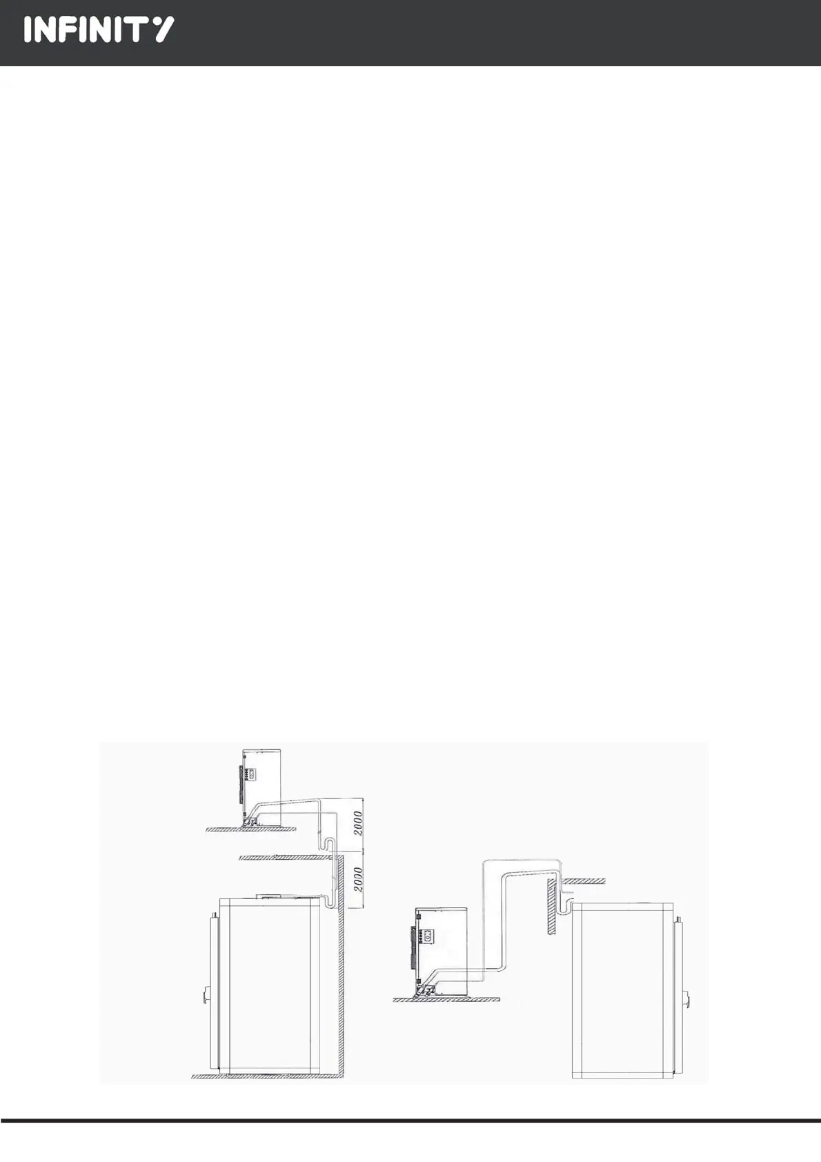
If the gas intake pipes have vertical sections, relevant syphons must be provided: the speed of gas intake in these vertical
sections must be at least 10-15 m/sec.
If it is necessary for the suction pipe to rise up as compared to the evaporator's position, we recommend a vertical rise and to
include syphons to allow for oil return.
To carry out this connection, install the liquid line, suction and hot gas piping in accordance with the diameter of the connec-
tions available on the machine.
The size of the pipes for distance between the evaporator and unit is up to 10 meters:
The inlet pipe diameter is 16 mm
The outlet pipe diameter is 22 mm
The hot gas pipe diameter is 16 mm
For greater lengths, size the diameters so that the right gas speed is guaranteed.
Always insulate the hot gas suction line with an anti-condensate pipe at least 13 mm thick.
It is crucial for the system to properly work and for compressor durability to correctly perform a vacuum test run of the system,
so as to ensure that air content and especially the humidity are below the tolerated values.
We recommend to run a vacuum test on both circuit sides, with the compressor valves shut. At any rate, the result aimed for
is a pressure of less than 5 Pa.
TO AVOID IRREPARABLE DAMAGE TO THE COMPRESSOR, DO NOT START IT RUNNING WHEN EMPTY WITHOUT HAVING FIRST SUPPLIED GAS.
DURING THE VACUUM AND GAS SUPPLY OPERATIONS, REMEMBER TO POWER THE COIL OF THE SOLENOID VALVE OF THE LIQUID LINE WITH
VOLTAGE, OR BY USING THE SPECIFIC MAGNETS.
After a vacuum test, the system must be fi lled with the type of refrigerant gas indicated on the rating plate. To correctly supply
the refrigerant gas, we recommend that after having run the vacuum, you pump part of the gas into compressor to "break the
void"; then, start the compressor running to intake the remaining portion of loaded gas.
To make sure the quantity of gas supplied is the right one, read the value on the gauges connected to the already installed
pressure inlets. The pressure values must be compatible with the machine's operating condition.
THE MIXTURES OF REFRIGERANT GAS MUST BE SUPPLIED TO THE SYSTEM IN THEIR LIQUID STATE
 Loading...