2
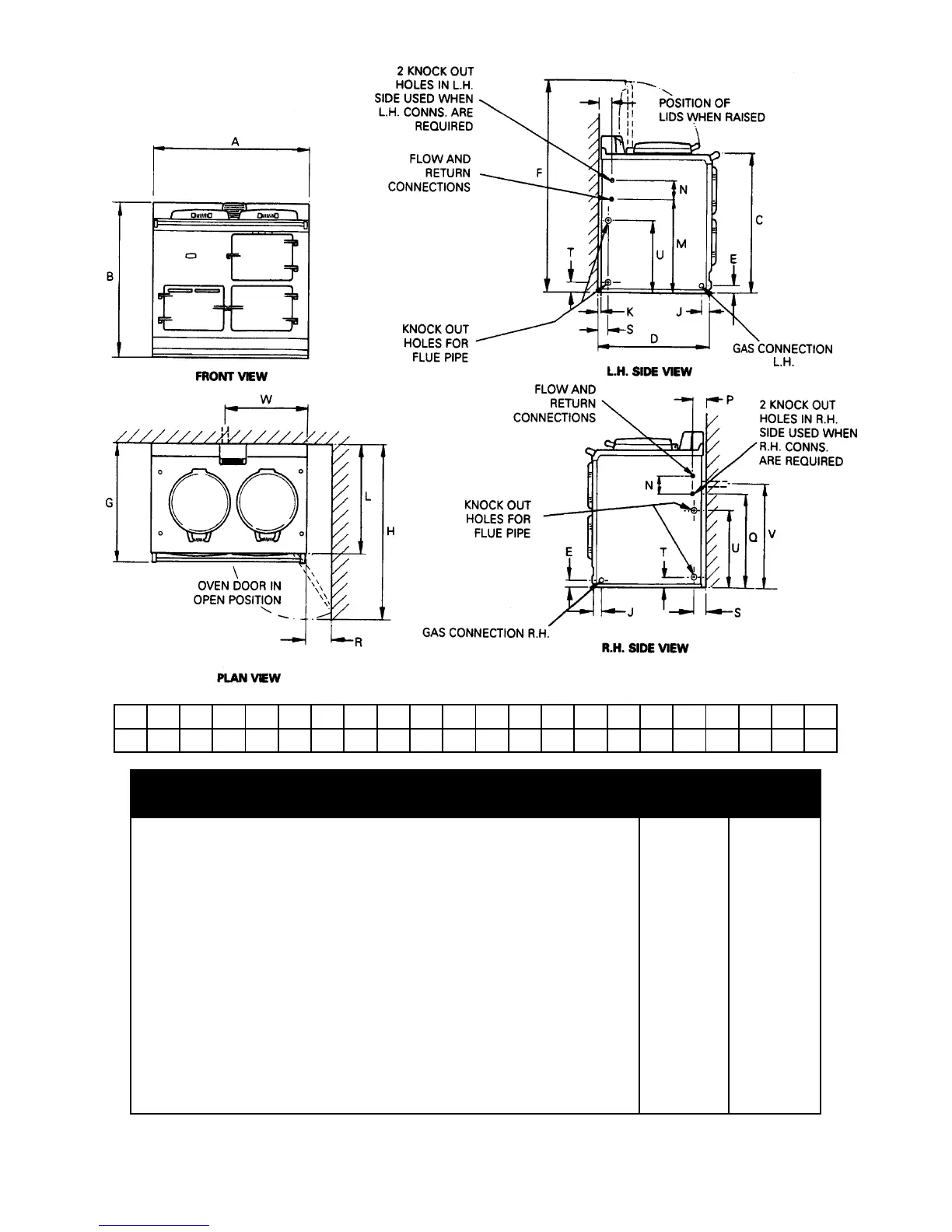
ABCDEFGHJKLMNPQ STUV
mm
987 967 851 679 41
1330
756
1125
39
3
698 499 127 41 530
R
116 48 65 375 595
W
667
NATURAL G20
MAXIMUM HEAT INPUT 5kW 5kW
Thermostat Bypass 100 or 120 120 or 140
Main Burner Injector 285 285
Pilot Injector N35 N35
Inlet Pressure 20mbar 20mbar
PROPANE G31
MAXIMUM HEAT INPUT
5kW (357g/h) 5kW (357g/h)
Thermostat Bypass 60 or 80 80 or 100
Main Burner Injector 180 180
Pilot Injector L23 L23
Inlet Pressure 37mbar 37mbar
Burner Pressure 28mbar 28mbar
Models GC and GCB Powered flue GC GCB
DESN 511187
For natural gas the gas valve outlet pressure is non adjustable, BUT for reference purposes only, a pressure
drop of 1-2 mbar can be observed between inlet and outlet pressures on a cold appliance.