32
(5) Mark a sign on the damper and rotate the crankshaft for a circle (360°). Follow the same steps to adjust the other
intake and exhaust valve clearances.
(6) Install the valve cover and tighten the cover bolts to 18 N·m.
Caution: The cover sealing strip should be replaced if it is damaged.
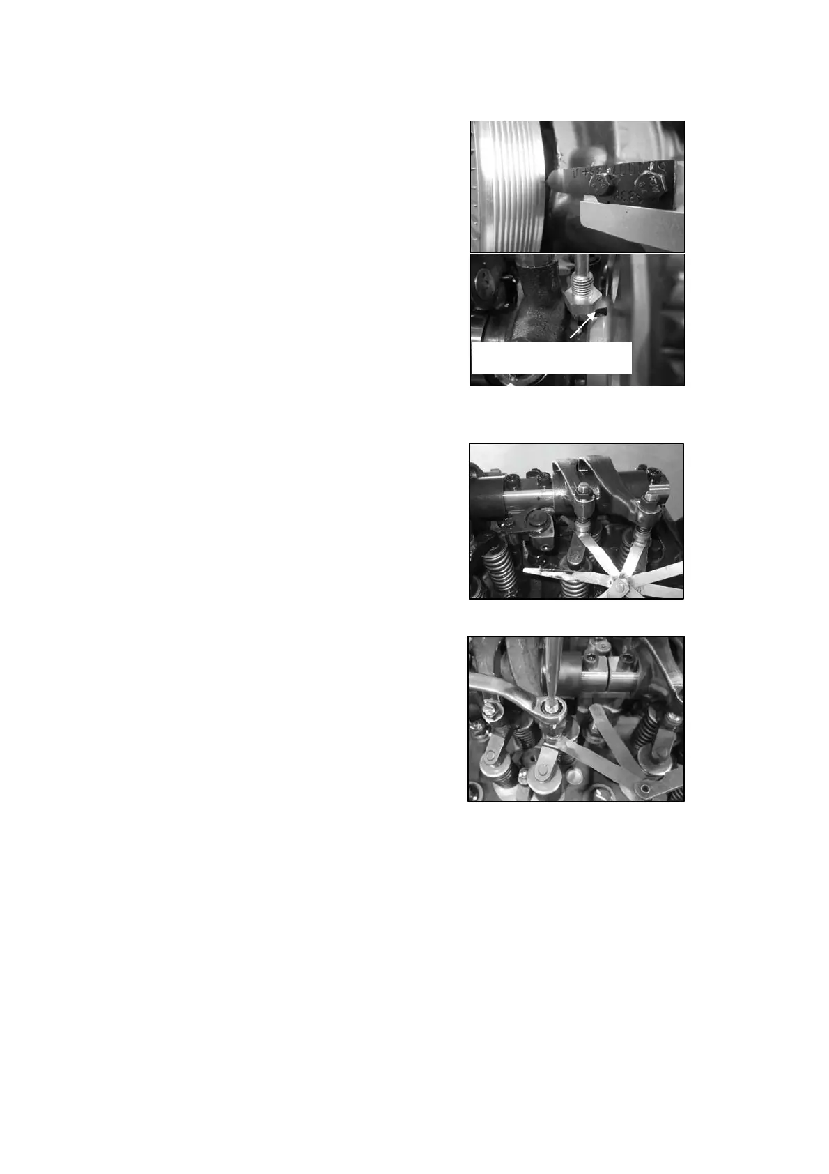
(3) Check the valve clearances with feeler gauge.
Check the intake valve clearance of No. 1, 2 and 4
cylinders, as well as the exhaust valve clearances of
No. 1, 3 and 5 cylinders.
Note: The clearance is correct when some resistance
is felt when the feeler gauge is slipped between the
valve bridge and the rocker arm.
(2) Crank the engine to position the first cylinder piston
at the top dead center on the compression stroke.
Note: When the point indicator points at the mark 0 in
the vibration damper and the cut in the camshaft gear
faces up, the piston of No. 1 cylinder is at the top dead
center on the compression stroke.
Cut in the camshaft gear
(4) If a valve clearance fails to meet the requirement,
loosen the valve clearance locknut on the
corresponding rocker arm, adjust the clearance to
specified value and tighten the locknut by 28 N·m.
Check the valve clearance again and it should not
change.
Valve clearance
Intake: 0.40 ± 0.08 mm
Exhaust: 0.65 ± 0.08 mm.